ESPRIT-to-VERICUT-Interface (ESV)
Prerequisites
ESV is a licensed software program that provides an ESPRIT to VERICUT data transfer connection. The interface is an executable that is designed to work with ESPRIT.
Versions supported:
Esprit 2011 (Build B18.1.6 or later)
CGTech Licensing:
Esprit Interface
Minimum VERICUT Version required:
VERICUT 7.1
Minimum VERICUT License Version required:
8.2
Configuration
To automatically install the ESPRIT to VERICUT interface (ESV), insert the VERICUT installation folder of the downloaded VERICUT installer. Next, run the esprit_interface_install.exe and follow the on-screen instructions.
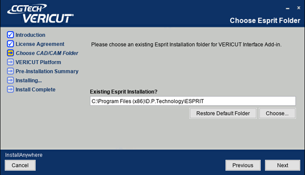
Installer: https://www.cgtech.com/previous-vericut-release

Manual installation
The following section describes how to install the ESPRIT-to-VERICUT Interface without using the installer. ESPRIT requires that Add-Ins write values to the registry, because of this, you must have administrator privileges to run these scripts.
First, create a directory named VericutAddin in your ESPRIT AddIns folder. If you have ESPRIT installed in the default location, the folder you will need to create will be at C:\Program Files (x86)\D.P.Technology\ESPRIT\AddIns\VericutAddin.
Next, copy all the provided source files into your VericutAddin directory.
Copy from C:\Program Files\CGTech\VERICUT x.x.x\windows64\esprit
Copy to C:\Program Files (x86)\D.P.Technology\ESPRIT\AddIns\VericutAddin
Register the interface
Next, you will need to register your files with the Windows registry and with ESPRIT so that it will be able to find the Add-In when starting up.
You will need to double-click the file register-vericut-addin-64.reg. After double-clicking the file, you will be asked to confirm if you want to add an entry to the registry. Select yes and you should receive a confirmation message that the value was added successfully to the registry.
NOTE: You must have Administrator privileges run register-vericut-addin-64.reg.
Environment variables
To enable Esprit to find the necessary VERICUT files, you also need to define three environment variables, CGTECH_INSTALL, CGTECH_PRODUCTS and LSHOST. CGTECH_SINGLE_PLATFORM and CGTECH_ESPV_LANGUAGE are optional.
| No. | Environment Variable | Example |
| 1 | CGTECH_INSTALL | C:\Program Files\CGTech\VERICUT x.x.x |
| 2 | CGTECH_PRODUCTS | C:\Program Files\CGTech\VERICUT x.x.x\windows64 |
| 3 | LSHOST | localhost |
| 4 | CGTECH_SINGLE_PLATFORM | YES |
| 5 | CGTECH_ESPV_LANGUAGE | C:\Program Files\CGTech\VERICUT x.x.x\windows64\Esprit\french\EspritRes.local |
CGTECH_INSTALL is set to the VERICUT installation folder. In the above table, x.x.x represents the VERICUT release number. For a typical VERICUT 9.5.3 installation this variable is set to C:\Program Files\CGTech\VERICUT 9.5.3\. Defining a value explicitly for the CGTECH_INSTALL environment variable is optional. It can be derived from the CGTECH_PRODUCTS environment variable value.
CGTECH_PRODUCTS is set to the folder for the specific operating system of the computer running VERICUT: "windows64". In the above table, x.x.x represents the VERICUT release number. For a typical VERICUT 9.5.3 installation this variable is set to C:\Program Files\CGTech\VERICUT 9.5.3\windows64.
LSHOST is set to the name of the license server computer.
CGTECH_SINGLE_PLATFORM=YES If you are using VERICUT single Platform then an additional environment variable needs to be defined for the interface.
CGTECH_ESPV_LANGUAGE If you want the interface to use something other than US English, the variable can specify a file of localized text. Versions for French, German, Italian, Chinese, Portuguese, and Japanese are supplied.
Use the Microsoft Windows Control Panel > System Properties > Advanced tab > Environment Variables feature to define these environment variables. See Microsoft Windows Help for more information.
To add an icon to the Toolbar
No action is required.
Microsoft Redistributables
The interface may require the Install of Windows C++ run-time libraries (Microsoft Redistributables). The Microsoft Redistributable vc_redist.x64.exe Installer is also available for download at: https://support.microsoft.com/en-ca/help/2977003/the-latest-supported-visual-c-downloads
Usage
The Esprit-to-VERICUT Interface (ESV) exports the Esprit manufacturing data to VERICUT, ESV addresses the below VERICUT setup requirements and then launches VERICUT with the simulation ready to play.
The VERICUT simulation requirements are:
1. Select a VMC (VERICUT Machine Configuration)
2. Select and orient stock, fixture and design models
3. Select NC Programs & Subroutines
4. Define Cutting tools
5. Define Work Offsets Tables
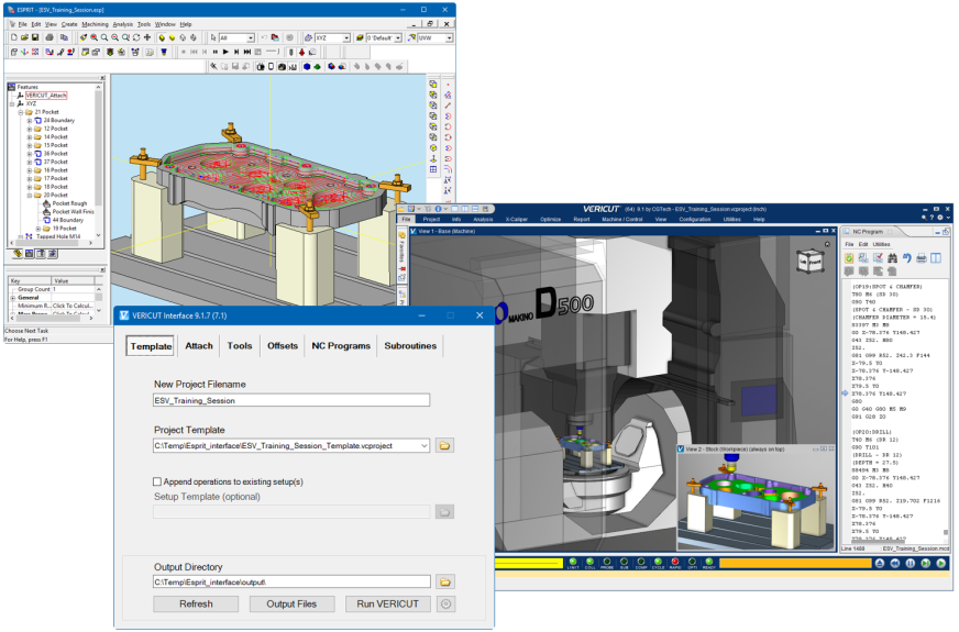
Accessing the ESPRIT-to-VERICUT Interface
From the Esprit Toolbar select Tools > VERICUT.
Note:ESV requires an active NC Manufacturing file running in order to interface with VERICUT.
User Interface & Operation
When you trigger ESV, you should see a window similar to this:
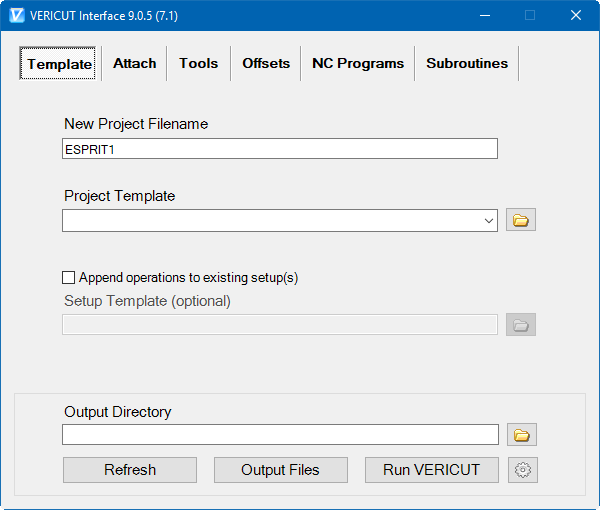
Note: The Interface Checks Out a license when the Interface is opened and then the Interface Checks In the license when the Interface is closed
The Template tab is used to specify a file name for the new project, a project template, the output directory that files will be written to, and optionally, a setup template. The New Project Filename and the Project Template fields must be filled in before you can move to another tab.
New Project Filename: Enter the "base" name for VERICUT files that will be created. By default, the name of the ESPRIT .esp file is used.
Project Template: Enter the /path/filename of an existing template file (.VcProject) that you want loaded in the text field or use the  (Browse) icon to display a file selection window and use it to specify the /path/filename. A template file is a previously defined VERICUT project file (.VcProject).
Append operations to existing setup(s): When toggled "on" (checked), the ESPRIT-to-VERICUT Interface will append the operations in the ESPRIT part file, to the setups that are already defined in your Project Template file, and setups from both files will be contained in the generated project file. Otherwise, and more typically, the imported ESPRIT part operations will be the only setups in the generated project file.
Setup Template: Enter the /path/filename of the Setup "template" file that you want loaded in the text field or use the  (Browse) icon to display a file selection window and use it to specify the /path/filename. A setup "template" is a previously defined VERICUT project file (.VcProject) containing files and settings required for VERICUT simulation. The Setup Template feature is only available when the Append operations to existing setup(s) feature is toggled “on” (checked). The following features are common to all VERICUT Interface window tabs.
Output Directory: Enter the \path\ in the text field to the directory where you want the VERICUT files output or use the  (Browse) icon to display a directory selection window and use it to specify the \path\.
NOTE: The Output Directory, Refresh, Output Files, Run VERICUT features and the Settings icon are common to all VERICUT Interface window tabs.
Attach tab
The Attach tab is to specify attach points for Esprit models in VERICUT. Attach tabs are be created by parsing through the machine file; there will be a separate tab for each 'attach' found in the machine file.
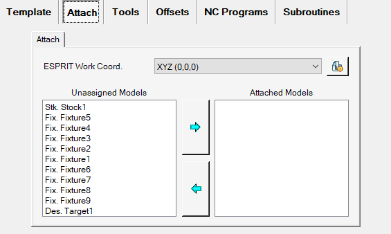
The drop-down menu at the top lets user to choose which ESPRIT work coordinate maps to which VERICUT attach point.
All model names are prefixed by their type: 'Stk' for stocks, 'Des' for designs, and 'Fix' for fixtures. Also, for parametric stock in Esprit, name is chosen same as their type i.e. 'Bar', 'Tube' or 'Casting', prefixed by "Graphics". Models can be moved from unassigned field to assigned field by selecting it and pressing right arrow button. If no models are selected, clicking the arrow will move the first entry to the other list. Multiple models can be selected by pressing 'Control' and 'Shift' keys. Clicking either arrow with nothing selected moves the first model from the unassigned list into the attached list. There is no mandatory requirement for selecting models. This step can be skipped and user can move on to next tab, without performing any operation here.
Sub-tabs: The VERICUT Interface window: Attach tab will have a sub-tab for each Attach component found in the specified Project Template file.

ESPRIT Work Coord: Use to specify which ESPRIT work coordinate maps to which VERICUT attach component.
Unassigned Models: The Unassigned Models list contains all models from the ESPRIT  Simulation Parameters that are designated as Stock, Target (Design) or Fixture. Or from the Machine Setup > General > Stock Configuration values.
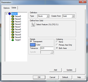

All model names will be prefixed by their type: "Stk" for stocks, "Des" for designs, and "Fix" for fixtures. In the case of turning machines, the stock can also be defined parametrically as “Bar”, “Tube” or “Casting” in Esprit. This will appear in the Esprit-to-VERICUT interface as “Stk. Parametric_Tube”, “Stk. Parametric_Bar” and “Stk. Parametric_Casting”, respectively. However, only “Bar” and “Tube” type parametric stocks are currently supported in the Esprit-to-VERICUT interface. You can use the Control and Shift keys on your keyboard to perform multi-selection.
Attached Models: The Attached Models list shows the Stock, Target (Design) and Fixture models that are associated with the “current” (the highlighted sub-tab) Attach component. Select the appropriate models in the Unassigned Models list and move them to the Attached Models list.
Use the  (Right Arrow) button to move selected (highlighted) models in the Unassigned Models list to the Attached Models list. If no models are selected, using the Right Arrow button will move the first model in the Unassigned Models list to the Attached Models list. You can use the Control and Shift keys on your keyboard to perform multi-selection. Use the
  (Left Arrow) button to move selected (highlighted) models in the Attached Models list to the Unassigned Models list. If no models are selected, using the Left Arrow button will move the first model in the Attached Models list to the Unassigned Models list.
Component Properties  — Stock, Fixture and Design model component names can be specified into respective text boxes, if they are preferred to be different then default names.

Tools tab
The Tools tab is used to specify where your tools will come from, and if you are using a multi-turret machine with one or more turrets whose tools need be oriented in the opposite direction, the Select Bottom Turret(s) option on this tab enables you to specify them.
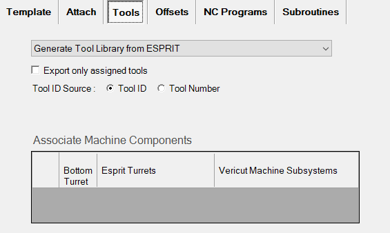
Select one of the following options from the pull-down list:
Generate Tool Library from ESPRIT: Choose this option to have the ESPRIT-to-VERICUT interface create a tool library using the tool data in ESPRIT.
Merge ESPRIT Tools with Template Tool Library: Choose this option to merge the tool library created by the ESPRIT-to-VERICUT Interface, with the tool library file stored in the Setup Template, and use the "merged" tool library rather than one created by the ESPRIT-to-VERICUT Interface.
Use Tools from Template Tool Library: Choose this option to use the tool library file stored in the Setup Template instead of one created by the ESPRIT-to- VERICUT Interface.
Use Existing Tool Library: Choose this option to specify a specific tool library to use. Enter the \path\filename of the tool library file in the Tool Library Name text field or use the Browse button to display a file selection window and use it to specify the \path\filename of the tool library file. If you choose to use this option, you must specify a valid Tool Library before moving to another tab.
Export only assigned tools: This checkbox is used to specify whether, interface needs to output only the tools which are assigned for manufacturing operations or all the tools specified in the Esprit project.
Tool ID Source: User can make a choice here between 'Tool ID' and 'Tool Number' specified in Esprit CAM system for specified tool, to become 'Tool ID' in VERICUT (to be exported as 'Tool ID' in TLS file). This option will not be visible when user has chosen "Use Existing Tool Library" option on "Tool Generation Scheme" pull-down list explained above.
Associate Machine Components: This mechanism is used to map the Esprit turret component with the corresponding VERICUT Machine subsystems, listed from specified VERICUT machine file. Correct pairings between Esprit turret components and VERICUT Machine subsystems help in writing tool-change list.

As seen above, there are three columns in the mechanism; all the Esprit Turrets components are listed in second column forming a separate row each. The check boxes are provided in the first column for each of the Esprit turret component to be specified as ‘Bottom’ Turret. Tools on the ‘bottom’ turret will be oriented in opposite direction inside VERICUT.
The last column, for each row, is a drop-down menu containing all Subsystems defined inside VERICUT machine file. User can select any of the Subsystem to make a pair with Esprit turret from second column, in the same row.
User defined Esprit Turret- VERICUT Subsystem pairings are stored into ‘Settings’ file.
If no such record found inside ‘Settings’ file, at the time of loading up the interface, interface will try to automatically assign correct VERICUT Machine subsystems to Esprit turret component. For that it will try to look for same name VERICUT turret/spindle component name as that Esprit turret, inside VERICUT machine file and the subsystem name of that VERICUT turret/spindle component will be used to form a pair with Esprit turret on the interface.
If no VERICUT turret/spindle component name is found as that of Esprit turret, first subsystem in the drop-down list will be assigned to form a pair, which user can change later to the desired one.
This mechanism is not needed for pure ‘Milling’ job; hence it will remain disabled for ‘Milling’ job and get enabled and populated only for ‘Turning’ and ‘Mill-Turn’ jobs.
Offsets tab
The features in the G-Code Offsets tab enable you to define VERICUT G-Code Tables used to orient the NC program to the part. For each subsystem, you may have any number of G-Code Tables, or None. There are no requirements for creating G-Code Tables. The use of this tab is optional and can be skipped if desired.
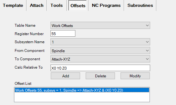
Sub-tabs: The VERICUT Interface window: G-Code Offsets tab will have a sub-tab for each subsystem found in specified Project Template file.

Table Name: Use to select the G-Code Table that you want to define. The Table Name pull-down list contains the following VERICUT G-Code tables: None, Program Zero, Work Offsets, and Base Work Offset. Choose the Table Name from the pull-down list.
Program Zero: The Program Zero table is used to specify the programmed zero location of a G-Code NC program file taking Tool Length Compensation into consideration.
Work Offsets: The Work Offsets table is used to store the work coordinate system offset (fixture offset) values.
Base Work Offset: The Base Work Offset table is used to specify the location from which work offsets are based.
Register Number: Use to specify the register number that will be used by VERICUT to access the corresponding table data. The register number may correspond to an offset register number, or an integer value, as required by a particular table. Enter the register number in the Register Number text field.
Subsystem Name: Use to specify name of the machine subsystem for which the table is being defined. Select the subsystem name from the pull-down list.
From Component: Enter the name of the component that represents the "from" point for determining the program zero offset or choose a component from the drop-down list. VERICUT will use the origin of the specified component. The default "From Component" is "tool".
To Component: Enter the name of a CSYS to represent the "to" point for determining the program zero offset or choose a component from the drop-down list. VERICUT will use the origin of the specified CSYS. The default "To CSYS" is a coordinate system named "Program_Zero".
Calc Relative to: This feature enables you to have a relational offset recalculated in the machine position where the offset will be used. The new position is immediately calculated and stored and therefore is not dependent on the machine position when the offset is activated.
Offset List: Displays the list of G-Code Table records currently defined.
Add: Adds a G-Code Table record to the Offset List based on the current Table Name, Register Number, Subsystem Name, 'From' Component and 'To' CSYS settings.
Modify: Modifies the G-Code Table record highlighted in the Offset List with the current Table Name, Register Number, Subsystem Name, 'From' Component and 'To' CSYS settings.
Delete: Deletes the G-Code Table record highlighted in the Offset List.
NC Programs tab
The features on the NC Programs tab enable you to generate NC Programs from the ESPRIT part file, or specify existing NC programs, to be passed to VERICUT. You must either: choose to generate an NC program, and provide a valid post processor file, or you must provide at least one existing NC program file.
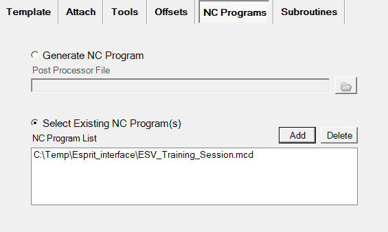
Generate NC Program: Use to create new G-Code NC program files from the ESPRIT part file using a specified postprocessor.
Post Processor File: Specify the /path/filename of the post processor that you want to use in the Post processor File text field, or click on the Browse button and use the file selection window that displays to specify the postprocessor file.
Select Existing NC Program(s): Use this feature to activate "NC Program List" and the Add and Delete buttons.
NC Program List: The NC Program List displays the NC programs that will be passed to VERICUT.
Add: Use the Add button to display a file selection window and use it to select the required NC program files.
Delete: Use to delete the highlighted NC program file(s) from the NC Program List.
Subroutines tab
The features on the Subroutines tab enable you to specify existing NC Subroutines, to be passed to VERICUT.
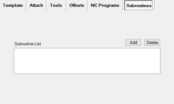
Subroutine List: The Subroutine List displays the NC Subroutines that will be passed to VERICUT.
Add: Use the Add button to display a file selection window and use it to select the required NC Subroutines files.
Delete: Use to delete the highlighted NC Subroutines file(s) from the Subroutine List.
The Preferences dialog can be launched by clicking on the  Settings button. This mechanism can be used to specify global options for interface display & behavior. These user options are global and are applicable to all sessions of the interface including the current session.
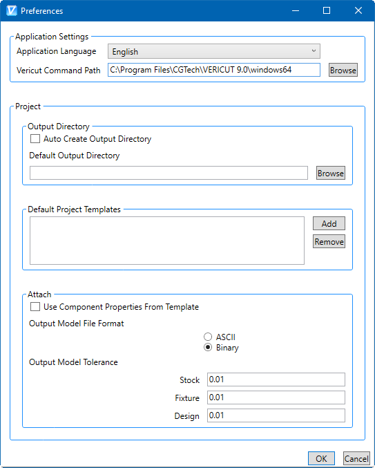
The dialog is divided into two sections; 'Application Settings' and 'Project Details'.
Application Language: User can change the language of the interface here, runtime, by selecting any of the language on the drop-down menu provided. If, for the language specified, local file will not be found to exist, error message will be displayed in red font.
VERICUT Command Path: User can edit/specify here the path for ‘commands’ folder which contains the VERICUT batch file, inside VERICUT installation directory.
Project:
Auto Create Output Directory
• User can choose to have interface 'auto create' output directory so that user does not have to provide one explicitly. This is possible by checking 'Auto Create Output Directory' check-box.
• In this case, every time user opens interface, a directory named 'output' will be created (if does not already exist) underneath the main directory in which corresponding Esprit project is located.
• This newly created 'output' directory will be chosen as an interface output directory and will be displayed to the user.
Default Output Directory
• Un-checking 'Auto Create Output Directory' checkbox enables 'Default Output Directory' text box and 'browse' button which otherwise are disabled.
• If user wants to output all interface exported files to one default folder, it is possible by providing path at 'Default Output Directory' text box. User can also locate path using 'Browse' button.
• User defined path here will be chosen as interface output directory and displayed on the interface in all future interface sessions.
Default Project Templates
• List of VERICUT project file that can be used as project templates can be specified here.
• Files listed here will be displayed in 'Project Directory' pull-down list on the main interface window.
Attach:
Use Component Properties from Template: if checked the output Stock, Fixture and Design component names will be taken from the VERICUT Template
Output Model File Format: User can define here output STL file format i.e., ASCII or Binary.
Output Model Tolerance: Tolerance values, separately for Stock, Fixture and Design models STL file, can be defined here. If any of the invalid tolerance values are found, the error message will appear alongside with the corresponding text box in red font. The default value for the tolerance is 0.1.
Output Files

Refresh: Refresh rescans for necessary data in the Esprit system, and the Settings file, and then loads the data back to the Esprit-to-VERICUT interface. If changes have been made to the Esprit project, Refresh needs to be used so that all of the Esprit project changes are updated in the Esprit-to-VERICUT interface data fields. Caution must be exercised when using the Refresh feature. If changes have been made to the settings in the Esprit-to-VERICUT interface and saved as described in the Settings File section above, using the Refresh feature would result in all of the current changes being lost and the Esprit-to-VERICUT interface data fields will revert back to their previous settings.
Output Files: Outputs all files, for all operations, including the selected models, tool library files, updated project and setup files, and the "operations" file that assembles all of this information into a VERICUT "project" file. It also updates the Settings File for the current ESPRIT part file.
Run VERICUT: Same as Output Files but also launches VERICUT.
Usage Variables
The following optional environment variables are available for use with the ESPRIT Interface.
| No. | Environment Variable | Example |
| 1 | CGTECH_ESPV_ACTIVITY | C:\Temp |
CGTECH_ESPV_ACTIVITY By default, activity file is also generated at local ‘Application Data’ directory inside CGTech/Esprit Interface directory. Example path would be same as that of ‘prefs’ file. However, by using environment variable ‘CGTECH_ESPV_ACTIVITY’ user can provide custom path for activity file generation.
Preferences
Preferences File
Also known as 'prefs' file, stores all user specified 'global' settings for interface operation. The settings stored are called 'global' because they are responsible for overall look & feel and operational behavior of the interface. They are not tied to any specific Esprit project. By default, Preferences file is generated at local 'Application Data' directory inside %APPDATA%/CGTech/Esprit/ directory.
Project Settings
File All of the fields into which a user requires to enter text are saved in an Esprit project specific settings file. The settings file is saved internally with the project. When the interface is opened, it first checks that whether the corresponding project has settings file saved along with it, and if so, loads the last saved settings from that. If no settings file is found for the project, all fields in the interface will remain blank.
In order to, save the settings file with the Esprit project, so that settings will be restored when opening the file later, the Esprit file must be saved. With that, settings file will automatically be updated with the current data of the interface, when user clicks on either of the Output Files or Run VERICUT button.
Activity File
The Esprit-to-Vericut interface tries its best to ensure a valid operation sequence, but when something does go wrong, an entry is added to the Activity File. Any attempt to execute an unsupported operation is also recorded here. At last, any undesirable behavior of the Esprit-to-Vericut Interface software is also recorded here. In the event of reporting a problem to CGTech technical support, it would be desirable to have 'Activity file' along with any example file. This will greatly expedite the process of resolving the problem. By default, activity file is generated at local 'Application Data' directory inside %APPDATA%/CGTech/Esprit/ directory. Example path would be same as that of 'prefs' file. However, by using environment variable CGTECH_ESPV_ACTIVITY user can provide custom path for activity file generation.
"Quick Start" training session
The ESPRIT-to-VERICUT Interface “Quick Start” training session is designed to quickly teach a VERICUT user the “basics” of using the Esprit Interface. The download includes: CAD/CAM files, VERICUT files, and step-by-step training sessions in PDF format.
Download: https://www.cgtech.com/solutions/interface-showrooms/
Note: to run the Quick Start files, Esprit V19.0.7.1578 or later is required.