ICAM V21 Release
These release notes describe the most significant V21 enhancements and problem corrections.
We hope you enjoy your new release of ICAM products and we sincerely welcome your feedback.
Systems and Packaging
Product Availability
System Manufacturer |
O/S Minimum Requirement |
Microsoft Windows 32-bit |
Vista, 7, 8, 8.1, Server 2008 |
Microsoft Windows 64-bit |
Vista, 7, 8, 8.1, Server 2008, 2008R2, 2012, 2012R2 |
Hewlett Packard 32-bit |
HP-UX 11.0 |
IBM 32-bit |
AIX 4.1.4 |
Sun Microsystems 32-bit |
Solaris 2.5.1 |
Quest is no longer available for UNIX builds. Post-processors to be run with Gener on UNIX systems must be developed using Quest on Windows systems. The ICAM database is fully compatible between UNIX and Windows systems.
This is quite likely the final release for all UNIX builds.
Installation
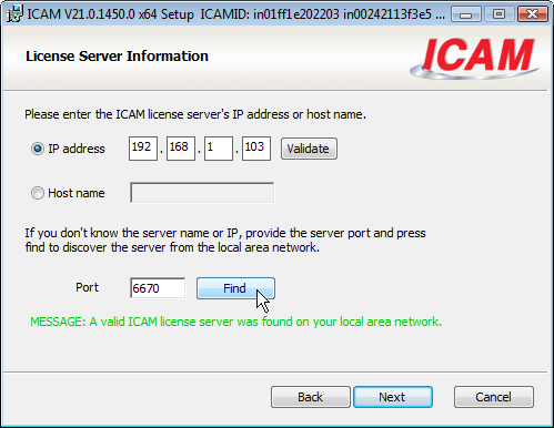
During a Windows Floating License Server installation, you will be given the choice of port number to use. The default, port 6667, matches the fixed port used in previous versions of the license server.
When installing other products on Windows client machines in a floating license network, you can now specify the port number to use when communicating with the server.
The Windows ICAMID Utility now allows you to select the port number when testing for a connection with the license server.
The UNIX floating license server now accepts a –p port command line switch to specify the port number.
Licensing
The license server is now at release 090. The primary difference between this latest release and the earlier 080 release is the support for a user specified port number. The port number can be specified during installation and changed after installation using the Floating License Manager (from the server computer).
On client systems, the server port number can now be specified in the icam.key file, by appending the port number to the server name or IP address. For example:
000 192.168.1.106:6670
New license options are available for SmartPATH, SmartCUT and SmartFEED modules. These are described starting on page 11.
The Windows Floating License Manager behaves differently depending on whether it is run from an ICAM Productivity Tools client installation, or from an ICAM Floating License Server installation.
When run from a client installation, the Setup menu provides a “Remote Server…” function to locate the floating license server on your network and optionally update the client icam.key file to point to the server.
When run from a server installation, there are additional and extended Setup menu options that let you choose the key file, the lost license timeout period, icamlm.log file contents and server port.
CAM-POST
Quest Developer’s
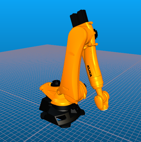
- The General Description / General Information section question #3 supports a new“Robotics” choice, available to those with CAM-POST Complete “p5” license. This first release of robotics is geared towards drilling, milling and trimming operations using standard CAM manufacturing programs.
 The Machine Description / Rotary Axes section includes a
new “DH params” tab where you define the 6 rotary joints of
the robot. An [Import] button allows the rotary joint information to
be imported from an existing Virtual Machine model. Alternately, the
joint information can input by hand, and later a model can be created
from the robot post-processor (via the “File»New»Model»
FromExistingPost” menu function).
The Machine Description / Rotary Axes section includes a
new “DH params” tab where you define the 6 rotary joints of
the robot. An [Import] button allows the rotary joint information to
be imported from an existing Virtual Machine model. Alternately, the
joint information can input by hand, and later a model can be created
from the robot post-processor (via the “File»New»Model»
FromExistingPost” menu function).The Control Description / Advanced 5D Machining section “RTCP” questions must be answered, since the control of the robot is restricted in this first release to virtual axes only.
The installation Samples folder contains post-processors and associated models for both a Puma and a Kuka robot.
A new question in the General Description / General Information section controls how merging lathe CLDATA commands are post-processed when both turrets are active. The choice of method should not have an impact on the generated NC code but it will affect how the code appears in the Gener listing, and it may affect macro processing.
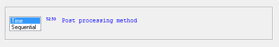
The “Time” method is the default, and causes processing to switch (as it always has) from one turret to the other based on the predicted machining time for each turret. Generated NC code will be produced in approximately the same order as the NC code will be processed at the machine.
The new “Sequential” method causes all CLDATA for the first turret to be post-processed up to the next synchronization mark, followed by all CLDATA for the second turret. For some this may be a preferred way of viewing the listing, and it may simplify macro processing.
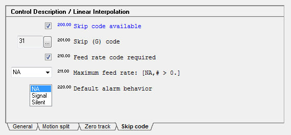
The Control Description / Linear Interpolation section has a series of new questions dealing with support for a “skip code”, used by the machine in probing operations to detect a touch. When used in a post-processor in combination with Virtual Machine, the skip-code function can be used to simulate probing and part transfer operations.
The Automatic Canned Cycles / General Drill Cycle Information section question #24.1 “Incremental secondary plane reference” now includes a new “±R” option in support of the Acramatic 950 cycle return W register. Answer “+R” to define the secondary clearance as being relative to the primary clearance, in a normal positive direction.
The Optional Post-processor Words / BREAK Command section has a new question #5.1 “Generate RETRCT with feed break” that can disable the automatic RETRCT to clearance plane (CLEARP or CLRSRF) that occurs when breaking a program on a feed motion.
The Optional Post-processor Words / CALSUB Command section has been revised as follows:
A subprogram repeat range now supports NC program labels for the start and end of the range of repeated NC code (prior to this release, the range could only be identified by N blocks). Labels allow the Siemens REPEAT and Heidenhain CALL LBL commands to be supported.
It is now possible to define both repeat range and subprogram call functionality in the same post-processor (e.g., Heidenhain CALL LBL and CALL PGM). New DEFSUB post-processor command syntax is available to define the preferred type to use in the NC code for any given subprogram definition in the CLDATA.
More control is available over the placement of subprograms and the timing of when they are output to tape.
The placement is controlled by question #4 “Subprogram output location” with choices being to output the subprogram in the same file as the main program NC code; or to output all subprograms together in a separate file; or to output each subprogram in its own file.
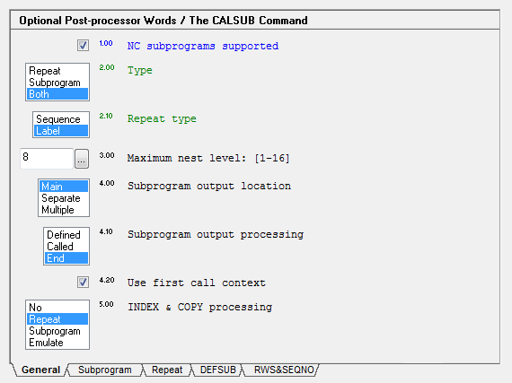
The timing of output is controlled by question #4.1 “Subprogram output processing” with choices being to output the subprogram when it is defined (i.e., DEFSUB), or when first called (CALSUB), or at the end of processing (FINI).
When deferring a subprogram’s output to the end of processing, a new question #4.2 “Use first call context” can be answered “Yes” to have the post-processor set itself to the machine status that was in effect when the subprogram was first called, before post-processing the subprogram for output to NC tape.
A new question #5 “INDEX & COPY processing” determines how the post-processor handles INDEX and COPY commands that were not processed by the CAM system (i.e., that are present in the CLDATA).
The INDEX & COPY choices depend on the types of subprograms that are available, or not, and include:
Choice |
Action |
|---|---|
No |
Ignore INDEX and COPY commands with a warning diagnostic. |
Repeat |
INDEX blocks are labeled where defined and called at each COPY. |
S ubprogram |
INDEX blocks define subprograms that are called where defined and also at each COPY. |
Emulate |
Expand the COPY blocks as the CAM system should have. |
The APT standard COPY command can define a transformation of the copied code. CAM-POST can support some types of transformations, using a local coordinate system (LCS) and/or incremental positioning. This can be controlled using the new DEFSUB/INDEX command, described on page 9.
Two new Post-processor Customization macros are available with this release:
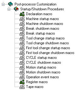 A new Declaration Macro provides a standard place for
GLOBAL, OBJECT and FUNCTN macro declarations. This macro was added as
part of an effort to help developers create more stable macro code as
well as catch misspellings and improper use of variables. More
information about the declaration macro can be found on page 28.
A new Declaration Macro provides a standard place for
GLOBAL, OBJECT and FUNCTN macro declarations. This macro was added as
part of an effort to help developers create more stable macro code as
well as catch misspellings and improper use of variables. More
information about the declaration macro can be found on page 28.A new Register Macro provides detailed control over the formatting of registers. This macro was added to provide a more targeted approach to NC tape editing than can be achieved by using either the Tape Macro or Tape Editor. More information about the register macro can be found on page 31.
The Build Tab now highlights errors in red.
The first line of the Diffs Tab, which identifies the objects being compared, now always stays visible, even when scrolling.
Gener Run-Time
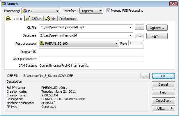
The Gener launch panel has been redesigned for V21.
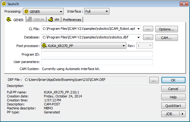
The new unified launch panel combines the activation of Gener post-processing, CeRun control emulation and Virtual Machine simulation all in a single interface. This was done in support of a new V21 PSE (Post/Simulation/Emulation) enhancement that allows Gener and CeRun to be run in parallel (so that CeRun simulates NC code as it is being created by Gener) or in series (so that CeRun begins simulation immediately after Gener completes post-processing). This new feature is described on page 25.
There is now a distinct panel for Virtual Machine simulation, which clearly indicates if simulation is enabled or not, and if enabled whether any information is missing. There are similar distinct panels for Gener and CeRun. A new Preferences panel groups various user-preference choices together for easy access.
There is a new “Save for review” preference, which if selected will cause Gener and CeRun to save their results at the end of processing so that you can later review the program using the Full interface.

Results are saved at the end of processing into a file having the same name as the listing, but with a file type of ZRJ. To review an NC program’s results, drag and drop the ZRJ file onto the launch panel or desktop icon (or open the results using the [Job] button), then press OK. The Full interface will be activated showing the results at the end of Gener or CeRun processing. These include:
Input, Output (Gener only) and Console window complete traces
Source window listing the input file
Diagnostic window listing all diagnostics
Virtual Machine simulation window
Controller window including TimeLine access to entire program
Material removal simulation in-process stock final state
View Listing and View NC code menu selections
The save-for-review function allows, for example, a program to be run in background mode and then later opened for more detailed review if necessary. The ZRJ file contains sufficient information to allow a program to be rewound and reprocessed if desired (although this is not recommended for production programs).
There have been a number of other changes to the launch to make settings more visible and/or easier to modify:
The run-time interface (i.e., Full, Progress, Minimized, Background) is now selected from a drop-down list at the top, instead of the old 2-part selection.
The selected CAM system is now clearly listed in the Gener panel.
The launch panel now clearly shows the full path and filename of the definitions file being used (in earlier releases this information was available in the CAM panel, but the path was not shown).
The [Help] button has been removed, but the F1 function key still brings up more detailed help, and tooltips are available for all input fields.
The Gener Full Interface has a new File»SaveForReview function that will save the current state of post-processing into a ZRJ file for later review. Explicitly saving the process inhibits the automatic save that normally occurs at the end of processing when the “save for review” launch panel preference is selected.
CAM-POST now supports merging milling operations on mill-turn machines. This means that APPLY/MILL commands are now valid within a HEAD/BOTH – HEAD/OFF block. This is especially useful for CAM systems such as CATIA, which output all aptsource for the upper turret, followed by all aptsource for the lower turret.
If Gener detects invalid merging, such as simultaneous milling and turning on the same workpiece, then it will output a diagnostic, but allow processing to continue.
The BREAK command now only retracts when breaking on a feed motion if a CLEARP or CLRSRF is in effect and the new BREAK section question #5.1 “Generate RETRCT with feed break” is answered in the affirmative. The BREAK command also treats high feed positioning motions (as defined using PPFUN/24) in the same way as RAPID motions when looking for suitable break point.
The following new commands and command options are available:
The post-processor now supports INDEX and COPY commands. Normally the post-processor does not see these commands, which are actually CAM system instructions, with INDEX commands identifying regions of code to be copied, and COPY commands causing the CLDATA to be repeated or repeatedly transformed a number of times.

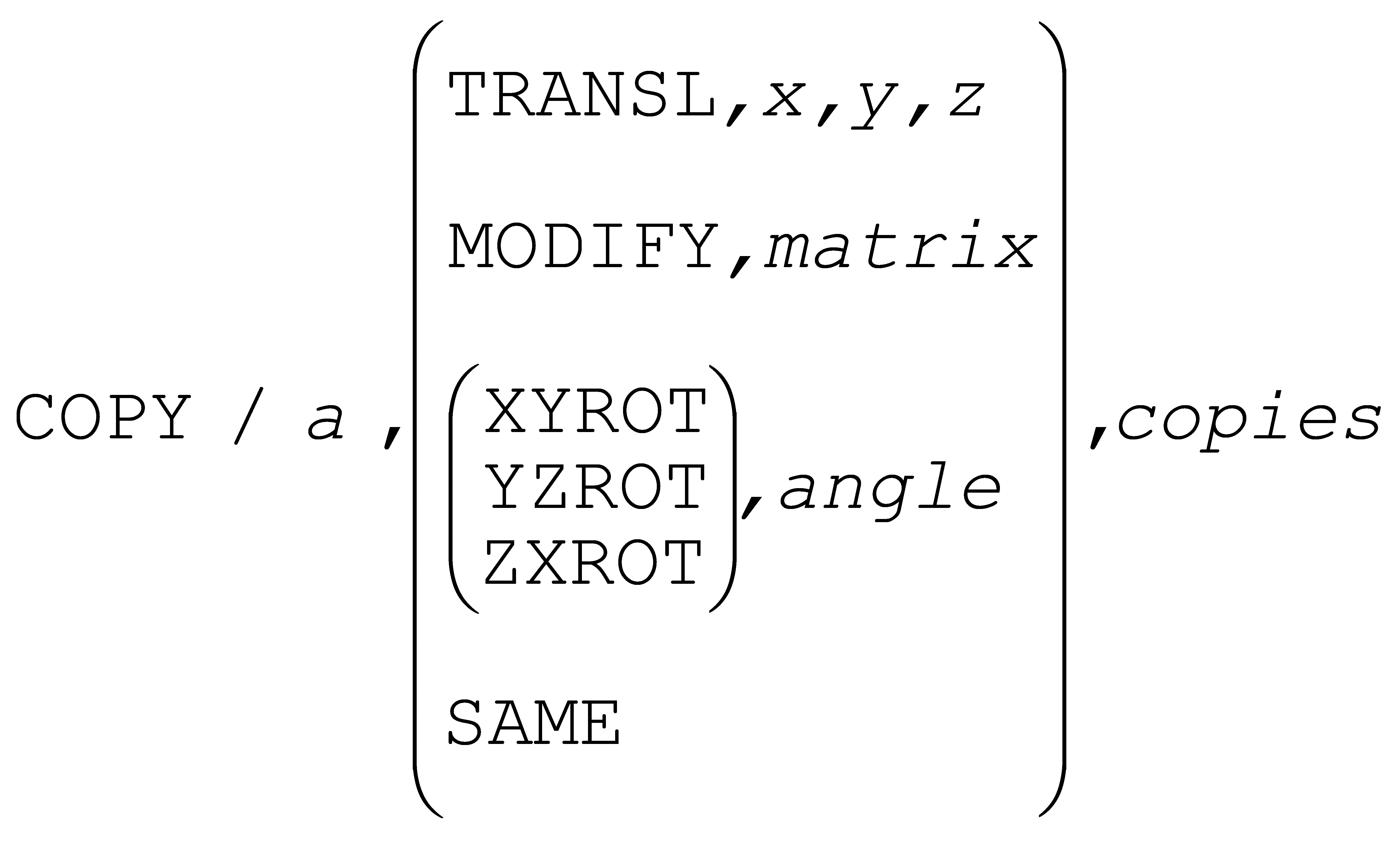
The post-processor can process INDEX and COPY in the same way as the CAM system would, or it can ignore these commands (with a diagnostic) as it has in past releases, or it can even use subprograms and/or repeat ranges to generate the required copies and transformations. These choices are controlled by the following new DEFSUB command:
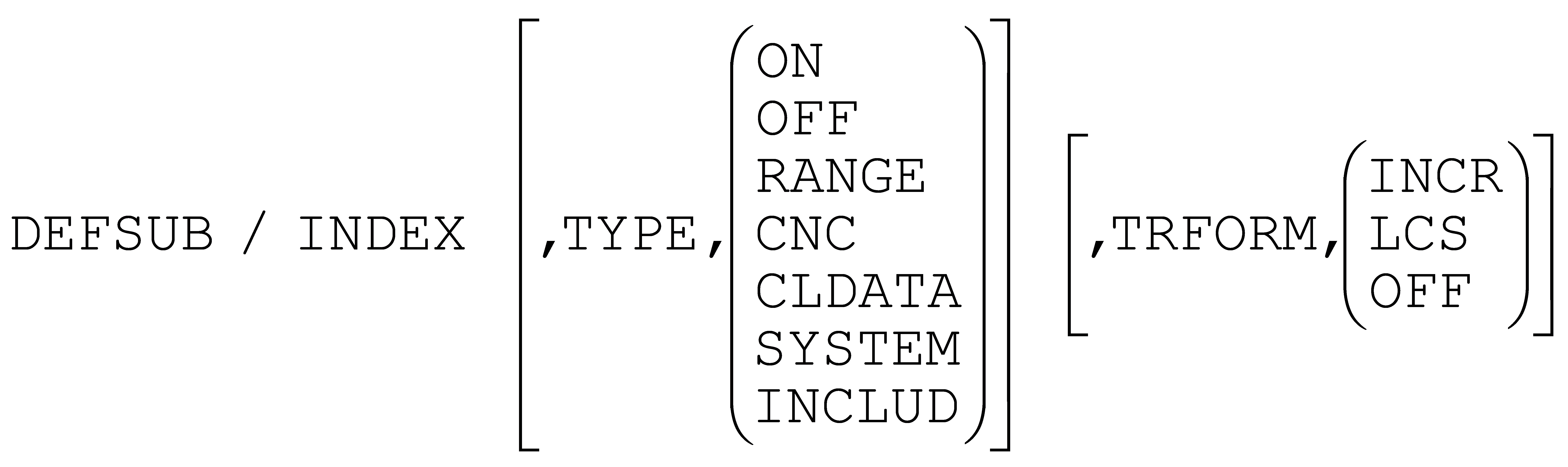
TYPE,OFF inhibits INDEX and COPY processing; ON uses whatever choice was selected by the post-processor author in the CALSUB section questions; and the remaining choices select how the copy will be generated.
TRFORM,INCR outputs the INDEX block code in incremental so that COPY transformation can be done by prepositioning prior to each subprogram call; LCS outputs the INDEX block as-is, but outputs an LCS (local coordinate system) instruction prior to each subprogram call; and OFF outputs all codes “as-is” and assumes that the post-processor author has handled the transformation requirements.
The CALSUB and DEFSUB commands have been enhanced to optionally support the couplet form of parameter definition as promoted by the ISO 4343 International Standard, with the use of ID before the subprogram identification and TYPE before the subprogram type.
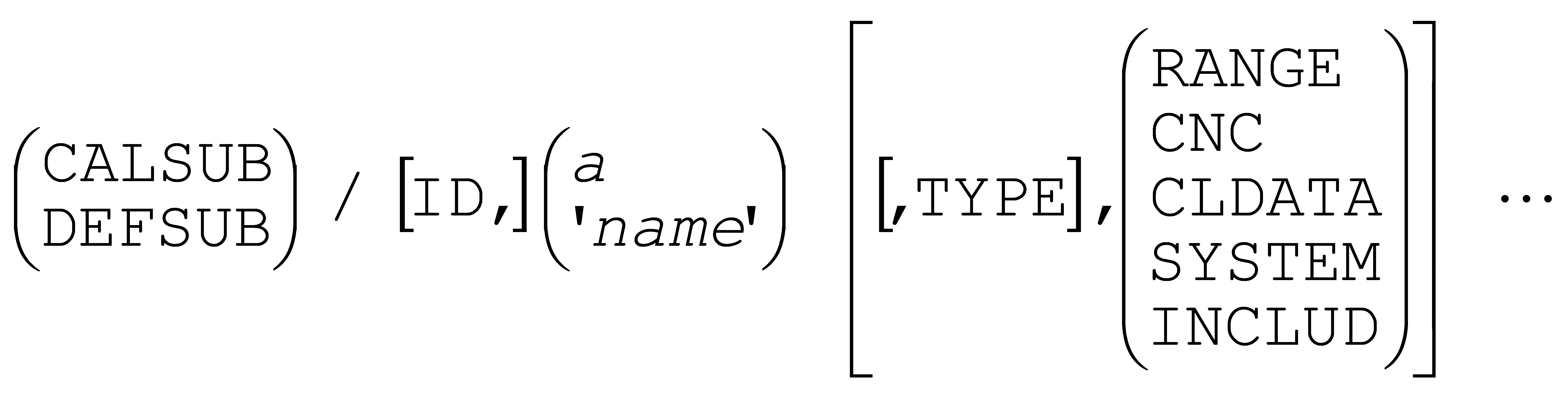
The RANGE and CNC options are new for this release. RANGE selects the repeat range method; CNC selects the subprogram method. CLDATA will select whichever method is available on the machine or will select subprograms if both methods are available. Other options have not changed.
The LINTOL command has a new option that affects how intermediate points are calculated along the motion being linearized.

In prior releases of CAM-POST, the linearized intermediate step distances would tend to decrease as the motion was subdivided, resulting in potentially very small subdivisions at the end of very large rotary moves. The linearization logic has been enhanced to eliminate the bias that was causing step sizes to progressively decrease, which has resulted in smoother stepping.
ON selects the new methodology, which is the default for V21. OFF selects the old behaviour, and is provided for compatibility purposes only. This new command is also available in V20-1350 and later releases, although OFF is the default for V20.
The MODE command has a new option to control the output of probe “skip” codes during linear interpolation motions.

Skip codes are generally hidden in subprograms purchased from probe vendors, but there may be occasions where skip codes must be generated by the post-processor.
ON causes skip codes to be output with subsequent feed motions until cancelled by OFF; NEXT outputs a skip code with the next motion only. The optional PART,IN and OUT control the generation of alarm behaviour codes, either resulting in an alarm at the machine if a skip is not triggered (IN) or an alarm if a skip is triggered (OUT).
When Gener is running with Virtual Machine simulation, skip code processing will be simulated provided that a probe object has been defined and is active (which is easily done using Virtual Machine probing functions).
SmartPATH
The SmartPATH licensed feature (sph210) was first introduced in V20. It automatically optimizes RAPID and high-feed positioning motions generated by the CAM system. SmartPATH works in conjunction with Virtual Machine to replace CAM generated positioning motions with time minimized, collision free positioning motions, based on the machine tool kinematics (e.g., head-head, table-table…), while respecting physical travel limitations and axes maximum positioning rates.
SmartPATH has been continually enhanced since it was first released. Many of these enhancements provide for additional safe clearances and were introduced to alleviate CNC operator concerns as well as to account for possible slight variations in positioning tool paths at the machine.
These enhancements (some available under V20) include:
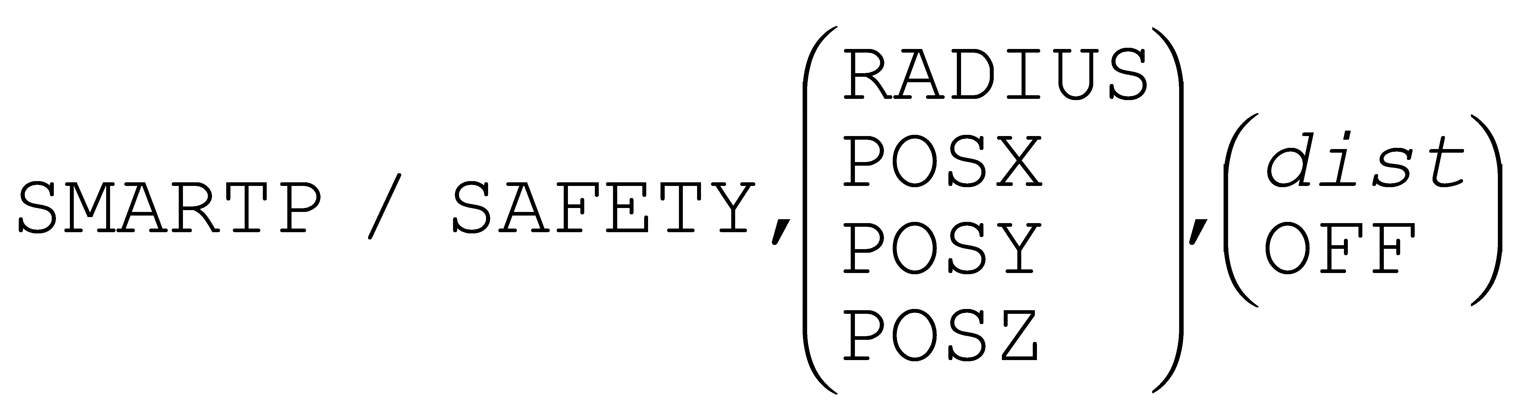
Recognition of the machine reference position(s) stored in the machine model so that motions to and from tool change and home positions can be accurately computed to avoid collisions. This feature is enabled or disabled as follows:

Additional safety clearances may be desired when moving between the machine reference frame (e.g., tool change position) and the workpiece or vice versa. A safe clearance distance can be optionally activated around the tool as well as around a group of components that have been predefined and named in the model.

By default the motion between machine reference and workpiece frames takes full advantage of the available travel of all axes of the machine. The following command defines a preferred region to use when moving between machine and workpiece frames.
The ability to apply post-processor SAFETY command motion splitting preferences to positioning motions generated by SmartPATH. This ensures that SmartPATH generated positioning motions follow approved shop practice where required.
The ability to automatically move clear of the part (e.g., pocket wall) at feed when leaving a cut so as to avoid dwell marks. And conversely, the ability to automatically position clear of a wall and engage at feed when entering a cut. This was first introduced in V20-1328.
The ability to control the velocity – either RAPID or high feed – of SmartPATH generated positioning motions. By default SmartPATH uses RAPID positioning when replacing CAM generated RAPID positioning motions, or uses high feed positioning if the CAM generated positioning path includes one or more high feed moves. This default can be overridden to force all RAPID, all high-feed, or the original behavior, using the following command:
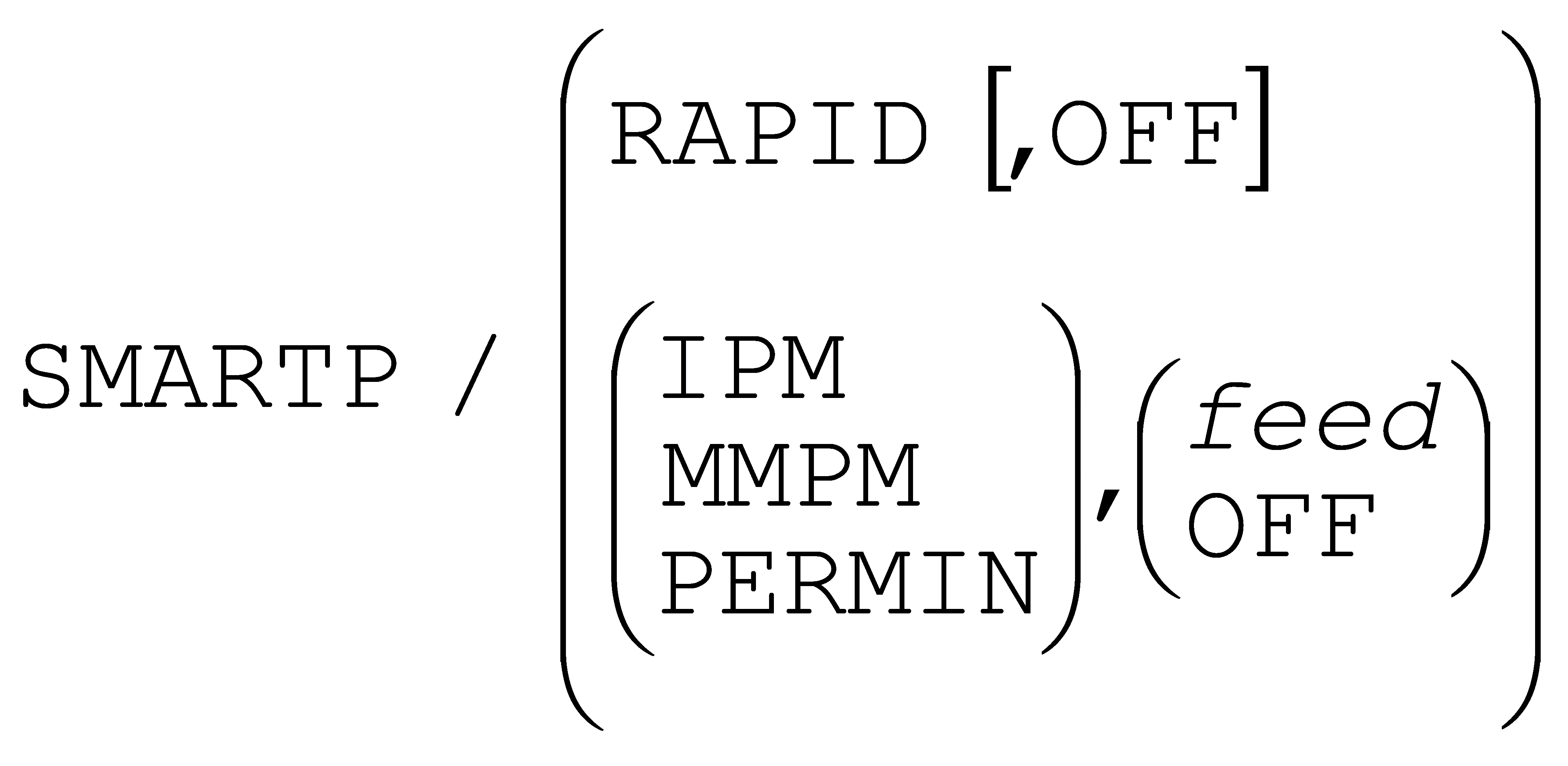
The ability to control the velocity – either programmed feed or high feed – of SmartPATH generated final approach, initial exit and wall clearance motions. These adjusted feeds are extensions of the SMARTP command syntax that defines the required clearance motion lengths.
The ability to automatically reduce safety distances where no possible solution can be found that respects the requested safety distances. In V20, if a solution could not be found, then SmartPATH would diagnose the problem and then retry without any safety distance at all. With V21, SmartPATH will diagnose the problem as before, but will also continue to look for a solution using progressively smaller clearance distances.
SmartPATH algorithms are continuously being improved, to provide more optimal results, all while reducing CPU computation time.
SmartCUT
The SmartCUT licensed feature (sct210) is new for V21. It uses material removal simulation to detect when the tool is not engaged with the material (i.e., is not cutting) while at the same time being programmed to move at a cutting feed. Where feasible SmartCUT will change these time wasting motions to RAPID or high-feed. This is commonly called an “Air-Cut” optimization, hence the name SmartCUT.
SmartCUT goes one step further, by detecting RAPID or high-feed motions that cut into the in-process stock and (in addition to warning the NC programmer) will automatically reduce the feed rate to the upcoming programmed feed to avoid tool breakage. Similarly, when leaving the material, SmartCUT will detect RAPID motions that cut the stock when leaving the part, and will automatically slow down these cutting motions to the last programmed feed.
SmartCUT is activated using the following command.

SmartCUT can use either high feed or rapid positioning when replacing air-cutting motions with positioning ones.
SmartCUT provides other settings that can: ignore air-cutting paths less than a specified length; enforce a minimum safe distance on air-cut positioning motions; and define minimum safe positioning approach and exit feed distances.
SmartCUT and SmartPATH when used together can significantly improve NC programs containing time wasting air cuts. SmartCUT will detect the start point and subsequent end points of air-cut segments as normal, but instead of increasing the velocity along the programmed path will instead use SmartPATH to compute the fastest path to the start of the next cut. SmartPATH takes into account the current state of the in-process stock as well as part, fixtures and machine components, when computing the shortest path to the start of cut.
SmartFEED
The SmartFEED licensed feature (sfd210) is new for V21. It uses material removal simulation to automatically recalculate the best machining feed rate based on the machine tool capabilities, tool reference cuts, and the real-time engagement of the cutting tool in the in-process stock material.
SmartFEED can be entirely controlled from post-processor commands, but also includes post-processor run-time dialogs for those who prefer a more interactive approach. SmartFEED is activated using the following command.

SmartFEED relies on reference cut information to perform material removal rate (MRR) based feed optimization. A reference cut defines, among other things, the depth, width feed and speed of a successful cut, which the software then uses to determine the feed and optionally speed to use for the feed motions present in the NC program.

SmartFEED permits limitations to be placed on the spindle speed, feed rate and spindle power.
SmartFEED provides other settings that can: impose limits on the growth of the program due to the generation of additional feed motions; define what constitutes a significant change in feed rate; define the material removal sampling rate (precision vs. CPU balance), and more.
Virtual Machine
Quest Developer’s
Models created or modified under V21 must now be Generated in order for them to be used with CAM-POST or Control Emulator. Models only had to be Saved in earlier releases, but V21 has introduced a new strong data typing feature of the macro processor that must be checked when generating a production-ready version of the model.
After saving or generating a model, the model descriptor will show the list of controllable axes as selected in the Machine Properties dialog Axis Mapping tab, listed in the order they are attached in the model. The model descriptor can be seen in the Database view, as well as in the Model Properties dialog Options tab. This feature was first introduced in V20-1321.
There is a new “head light” lighting control for V21. The head light control defines a light source that is directly behind the camera and is directed into the scene. This optional light source makes it easier to view the workpiece or machine from the rear of the model – areas of the simulation environment where typical light placement doesn’t reach. As with all other lights, you can control the intensity and colour of the head light.
It is now possible to import multiple STL files in a single operation. First select a node in the model navigator tree, then select Simulation»Construct Entity»Import and finally, choose all of the STL files to be imported at that node. STL import now also recognizes and supports files containing multiple bodies. These features were first introduced in V20-1405.
A new Rename branch RMB (right-mouse button) context menu function is now available in the model navigator, which recursively and consistently renames all entities in the selected branch. All entities and sub-entities matching a wildcard specification are renamed to a user-specified target name that can contain an incrementing numeric and/or textual string. This feature was first introduced in V20-1331.
Gener & CeRun Run-Time
 The Virtual Machine simulation window has undergone a
number of enhancements, as listed below. With the exception of the
cross section and tool path display features, all of these
enhancements are also available with Quest during model development.
The Virtual Machine simulation window has undergone a
number of enhancements, as listed below. With the exception of the
cross section and tool path display features, all of these
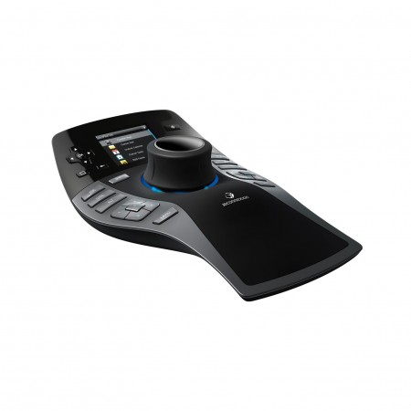
enhancements are also available with Quest during model development.Virtual Machine now supports 3D mouse devices from 3dconnexion, including the SpaceExplorer, SpaceNavigator, SpacePilot and SpaceMouse.
Virtual Machine has its own unique ways of manipulating objects on the screen using a combination of keyboard keys, mouse buttons and mouse movements, which are different from those used by the CAM system. Recognizing that this can be a source of confusion, Virtual Machine has now been enhanced to mimic the basic object manipulation features of CATIA, Mastercam and NX. The mouse “scheme” is selected from the Simulation»Options dialog Misc tab in Quest, Gener or CeRun.
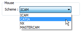
Basic supported functionality includes the keyboard and mouse inputs required to rotate, pan and zoom the window as well as to select objects. All other keyboard and mouse functions continue to follow the original ICAM scheme.
Two new measurement capabilities have been added.
It is now possible to select Kinematic objects when measuring. For example, the spindle control point, stock mount point, linear and rotary axes can be selected as a target point or edge and then measured against other objects in the window.
The radius and center of a hole, boss or corner can now be measured by selecting any combination of 3 points or edges – the midpoint of the edge is used – along the circumference of the arc.

Radius and center measurements are enabled by selecting the circled button in the VM Measure toolbar, as shown above.
A new cross section feature is available to section the in-process stock for better visibility and measurement purposes. Cross sectioning is controlled from the Simulation»Show»Cross Section menu as well as from the new VM Cross Section toolbar.

The four leftmost buttons define where the section plane will occur,
either along a standard datum with respect to the stock mount point, or
along a custom plane chosen using the same functionality as for
measurements. The sectioning function hides in-process stock on one side
of the section plane; the  Invert Plane button switches the
side that is hidden. The
Invert Plane button switches the
side that is hidden. The  Show Grid button toggles a grid
display on the section plane. The two rightmost buttons and the numeric
input field can be used to offset the section plane from the one
initially selected.
Show Grid button toggles a grid
display on the section plane. The two rightmost buttons and the numeric
input field can be used to offset the section plane from the one
initially selected.
Cross sectioning does not affect the in-process stock; it only affects the visibility of the stock. Collisions and material removal functions will continue to operate as normal, even when the stock is sectioned.
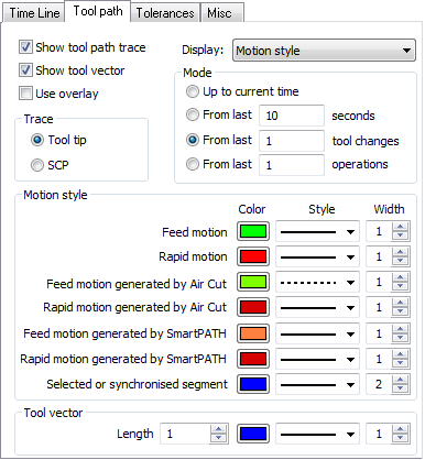
The tool-path display has enhanced to:
show the tool axis vector,
show the last “n” tools or operations, and
permit the customization of tool path line style, width and color.
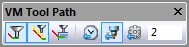
The new VM Tool-Path toolbar has controls to choose between a tool-path trace limited by time, tools or operations. The toolbar also has a button to enable/disable the display of tool-axis vectors.
The Simulation»Options dialog Tool Path tab has the same controls as above, plus new color and style controls for different types of motions. In particular, tool paths modified by SmartPATH, SmartCUT and SmartFEED can be identified by style, width or color, so that the effects of these optimization features are more readily apparent.
The VM Mode toolbar has two new buttons (shown circled below) that can be used to temporarily inhibit material removal simulation (MRS) and tool vs. part gouge detection.
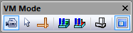
When the  “Pause Material Removal” menu bar selection
is active, the in-process stock and machinable fixtures will not be
affected by the cutting action of the tool. Temporarily inhibiting MRS
can be useful to ignore further invalid cutting actions of a tool,
during the early simulation phase of a manufacturing program. Also, when
used with Run»Restart a program can be quickly run once without MRS, and
if necessary a second time with MRS following the restart, without
having to change the “Enable Material Removal Simulation” setting in the
launch panel VM pane.
“Pause Material Removal” menu bar selection
is active, the in-process stock and machinable fixtures will not be
affected by the cutting action of the tool. Temporarily inhibiting MRS
can be useful to ignore further invalid cutting actions of a tool,
during the early simulation phase of a manufacturing program. Also, when
used with Run»Restart a program can be quickly run once without MRS, and
if necessary a second time with MRS following the restart, without
having to change the “Enable Material Removal Simulation” setting in the
launch panel VM pane.
When the  “Pause Gouge Detection” menu bar selection is
active, interference (i.e., collisions) will no longer be diagnosed
between the cutting tool and the design part. Temporarily inhibiting
tool/part collisions can be useful to speed up scribing or engraving
operations, if the part design does not include the image being scribed
or engraved.
“Pause Gouge Detection” menu bar selection is
active, interference (i.e., collisions) will no longer be diagnosed
between the cutting tool and the design part. Temporarily inhibiting
tool/part collisions can be useful to speed up scribing or engraving
operations, if the part design does not include the image being scribed
or engraved.
Virtual Machine has a new Simulation Manager window, which lists all of the components included in the simulation (i.e., tools, stock, part and fixtures) and where they are attached to the model. For example, tools will be shown attached to tool pockets, fixtures and workpiece will be shown attached to stock mount points.
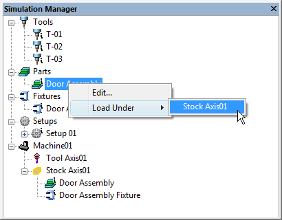 Double-clicking on a component or group header will activate
a dialog that permits modification of the selected component. As well,
pressing the RMB (right mouse button) on any component or group header
will list the actions that are available with the selected entry.
Double-clicking on a component or group header will activate
a dialog that permits modification of the selected component. As well,
pressing the RMB (right mouse button) on any component or group header
will list the actions that are available with the selected entry.
The Simulation Manager supports the concept of multiple setups. The initial configuration is “Setup 01”. Additional setup configurations can be created, either by copying and editing a similar configuration, or by creating one from scratch. The Simulation Manager supports drag & drop, to allow components to be easily attached or detached as required.
Switching between setups can be done by specifying the new LOAD/SETUP command in the input CLDATA, or by calling the new $FMSSETUP() function in either the Gener or CeRun macro processor. For visualization and testing purposes, setups can be manually selected by double clicking on the setup name.
The CATIA and Mastercam Manufacturing Extractors have been enhanced to recognize multiple setups as defined by the CAM system and automatically create the setup configurations inside Virtual Machine.
The Part and Stock object concept has been reviewed to simplify their usage. In V21 a Part object is composed of a Stock component representing the raw material to be cut and a Design component representing the planned result. The Design object is used for both gouge detection and part comparison. Stock and Design components are moved together by moving the Part object. The Stock/Part/Fixture dialog was revised and is now called the Part/Fixture dialog. Changes to the Part tab allow the Stock and Design components to be viewed or modified from a single tab.
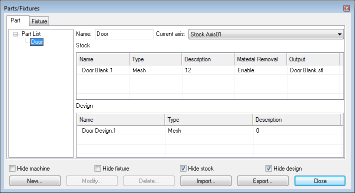
A new Output field for Stock components defines the name of a file where the final in-process stock will be saved in STL format at the end of processing. Manufacturing Extractors that support multi-setup will automatically set this field.
The in-process stock can also be saved at any time, either by selecting a stock component (note: it must have its “Material Removal” property enabled) and pressing the Export button, or under macro control using the new $FMSESF function (described on page 34)
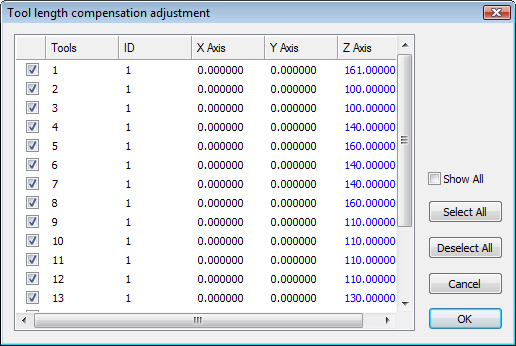 The Simulation»Tools/Holders/Heads dialog has been
enhanced to validate changes to tool and holder dimensions against
the Controller window tool and diameter compensation amounts. If the
tool compensation amounts do not agree with the tool definitions, a
dialog will appear (shown at right) listing the suggested tool
compensation changes highlighted in blue. Selecting OK will
automatically adjust the tool compensation for selected tools.
The Simulation»Tools/Holders/Heads dialog has been
enhanced to validate changes to tool and holder dimensions against
the Controller window tool and diameter compensation amounts. If the
tool compensation amounts do not agree with the tool definitions, a
dialog will appear (shown at right) listing the suggested tool
compensation changes highlighted in blue. Selecting OK will
automatically adjust the tool compensation for selected tools.
The Controller window Tool Compensation tab also has a new  button that can be selected at any time to check for consistency between
tool length compensation settings and the tools they are based on.
button that can be selected at any time to check for consistency between
tool length compensation settings and the tools they are based on.
The Time Line has been further improved for V21.
The Time Line window now provides Tooltips, which describe the collision, overtravel, tool, etcetera, event of interest under the cursor. Tooltips identify the start and ending time of the event as well as other pertinent information. For example, Spindle tooltips indicate the spindle speed and direction of rotation. Time Line tooltips can be enabled or disabled from the Simulation»Options dialog Time Line tab.
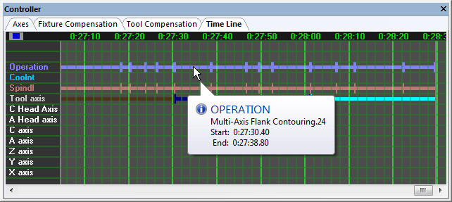
Tool and Operation names now also appear in the Time Line. With Gener operations are defined by the OPTYPE command; with CeRun operations are defined by setting the $OPNAME system variable. On multi-channel machines (e.g., merging lathes) there will be one Operation display line per channel, which can aid analysis of program synchronization. Tool and operation names are also now listed in the HUD (heads-up display).
Navigation and synchronization in the Time Line window have been improved by enabling the CTRL+HOME and CTRL+END key combinations, which synchronize the simulation to the start or end of processing. The F3 and SHIFT+F3 Find Next and Find Previous keys now cause a synchronization to occur as each event is found. Double-clicking in the Time Line window will cause a synchronization to occur at the selected time.
Probe touch events can now be optionally seen and searched for in the Time Line window, by enabling the Simulation»Options dialog Time Line tab “include probe touch events in Time Line find” setting. When enabled, searching for a next/previous collision will cause the simulation to synchronize at probe touches.
The Time Line can now better handle very long jobs; processes having a duration of up to 4 weeks can now be supported. In addition, improvements to the navigation algorithm now permit near instantaneous traversal between points of interest in the Time Line.
When running with SmartFEED, the Time Line window can switch between its normal display (e.g., collisions, overtravel…) and a feed optimization display. This second mode shows the effects of SmartFEED by graphically illustrating the cutting process.
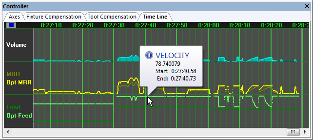
Time based graphs can be produced for any combination of the following:
The volume of material being removed
The programmed and/or optimized MRR (Material Removal Rate)
The programmed and/or optimized feed rate
The Simulation»Options dialog has been redesigned to organized option settings into separate Time Line, Tool Path, Tolerance and Miscellaneous tab pages.
|
|
|---|---|
|
|
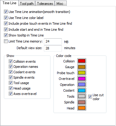
All tolerance related settings are now grouped together in the Tolerance tab.
Control Emulator
Quest Developer’s
The following features and functions described earlier in the CAM-POST Developer’s release notes (starting on page 4) also apply to Control Emulator:
Robotics machine type
Acramatic 950 cycle return “W” register
New REPEAT label range type
Support for both REPEAT and regular subprograms on the same machine
Probe skip code
Control Emulator and Post-processor development share many of the same questions in the Quest developer module, which is why it is possible to quickly develop a Control Emulator starting from a proven post-processor. Common questions have now been edited to remove the post-processing bias present in many questions. Also, questions that relate only to post-processing functions, or to functions not supported in the Control Emulator, will no longer appear when developing control emulators.
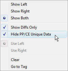 When using the Diff function to compare a post-processor
with a control emulator, a new “Hide PP/CE Unique Data” option
when selected will perform the comparison on only those portions of
the post-processor and control emulator that are common to both. So
for example, questions concerning how PPRINT should be post-processed
will not be listed as being different, because control emulator
development does not ask about PPRINT.
When using the Diff function to compare a post-processor
with a control emulator, a new “Hide PP/CE Unique Data” option
when selected will perform the comparison on only those portions of
the post-processor and control emulator that are common to both. So
for example, questions concerning how PPRINT should be post-processed
will not be listed as being different, because control emulator
development does not ask about PPRINT.Control Emulator uses pre-processors to handle advanced CNC functionality that is not included in the Questionnaire. This includes for example support of variables and functions in NC code, and support for looping and branching.
The following is a brief synopsis of enhancements made to each of the pre-processors. The CeRun on-line help defines the complete functionality for each pre-processor:
FANUC
C style && and || operators
IF, ELSE and ENDIF blocks
G66.1 modal subprogram call
Macro call using G, M, T, S, B and other addresses
New $FCEPP(‘PROCESS’,’MESSAGES’,logical) function call optionally disables Console trace window messages
HEIDENHAIN
Removed Console trace window messages identifying ISO or Conversational processing modes
SIEMENS
Improved DEFINE functionality, including lower and upper bound setting and support for up to 3 dimensional arrays
REDEF variable instruction
AXIS variable type
FRAME variable type
Use of FRAME variables in CTRANS(), CFINE(), CROT(), CSCALE() and CMIRROR() functions
Support for $P_UIFRNUM, $P_UIFR[n], $P_BFRAME, $P_IFRAME and $P_PFRAME variables based on CeRun and Virtual Machine kernel frame information
New $FCEPP(‘APPLYFRAMES’,logical) function call optionally disables built-in frame variable support
Support for $P_MC[x] variable where “x” matches CeRun code group
GOTOC and GOTOS branch instructions
- Added following functions:– AC(x), IC(x)– BOUND(x,y,z)– MINVAL(x,y), MAXVAL(x,y)– ROUNDUP(x)– SETAL(n,string)
Control Emulation is now integrated with DELMIA V5 and DELMIA V6.
DELMIA V6 integration permits the simulation of mill-turn and merging lathe CNC machines, which is not possible with V5.
The General Description / Integration section has new DELMIA questions dealing with multi-channel machines. A new question #120 “number of channels” defines the number of independent sets of controllable axes; answer “2” for a typical merging lathe. Subsequent questions will allow the association of DELMIA axes with each of the available channels.
A restricted set of Virtual Machine macro functions can be used to identify and move auxiliary axes of the DELMIA model, such as the tail stock, steady rests, etc. This is further described on page 35.
CeRun Run-Time
As mentioned in the CAM-POST enhancements, Gener and CeRun now share the same launch panel. This was done in support of a new V21 PSE (Post/Simulation/Emulation) enhancement that allows Gener and CeRun to be run in parallel or in series.
A new “Merged PSE Processing” launch panel setting enables the running of Gener and CeRun in parallel. This means that as each block of NC code is created by Gener, it is then immediately processed by CeRun. The Virtual Machine simulation window shows and diagnoses (i.e., checks collisions and over-travels) the results of the CeRun simulation. If desired the simulation window can also show the post-processor’s interpretation of the machine position and material removal state, which can be enabled by a new “Include GENER simulation under merged PSE” setting in the VM launch panel tab.
Parallel processing is not available if either the post processor or control emulator is composite or for a merging lathe machine. In this case the “Merged PSE Processing” launch panel setting will not be selectable. After selecting OK from the launch panel, Gener will first run to completion and then CeRun will begin, reading the NC code created during post-processing.
There are a number of other interesting enhancements to the launch panel, which are described starting on page 7.
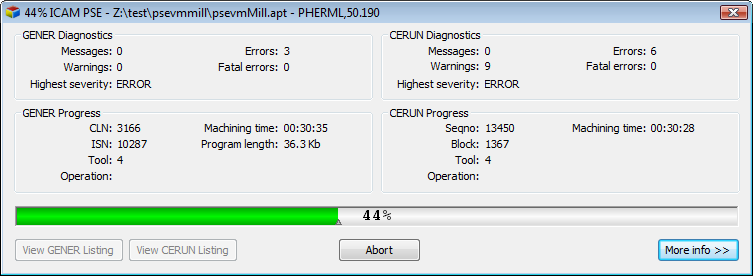
Gener and CeRun must share the Statistics window and the Full interface window when running in the new parallel processing mode. This has required some changes to the interface, as described below.
The Statistics window shows the state of both processes, side by side. At the end of processing, separate buttons provide quick access to the Gener and CeRun listings.
The Full interface uses the multi-kernel capabilities introduced in V20, to cleanly separate Gener and CeRun tracing and debugging.
The Diagnostic window and Trace windows (Input, Output, Console and Macro) all include buttons at the upper left that allow one or the other or both Gener and CeRun diagnostics and traces to be shown. A “link” button appearing at the upper right of each window can be toggled to change the information shown for individual windows (e.g., trace only Gener input and only CeRun output).
The contents of the debugging Source, Stack and Variables windows are controlled by the Multi-Kernel toolbar, which lists the two available kernels: Gener or CeRun. When, for example, the Gener kernel is selected, the Source window shows the CLDATA file and post-processor macros, the Call Stack window shows the post-processor calling stack, and the Variables window shows post-processor variables. When the CeRun kernel is selected, the Source window shows the NC code (generated to the current time) and control emulator macros, the Call Stack window shows the control emulator calling stack, and the Variables window shows control emulator variables.
The Simulation window by default shows the results from control emulation, but when the “Include GENER simulation under merged PSE” setting in the VM launch panel tab is selected, then the Multi-Kernel toolbar selects which of the two Virtual Machine sessions to view (they should be identical within a block or two).
The Status bar shows information for both processes, but the progress completion bar is based on progression through the CLDATA file by the post-processor.
Gener and CeRun each run independently when running in series, but there have been some changes made to the interface that are necessary because of the automatic start of CeRun processing after Gener processing has completed.
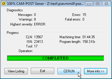 The Gener Statistics window has a new CeRun button that
can be activated once post-processing has completed. This provides an
opportunity to view the post-processor results before CeRun
processing is started.
The Gener Statistics window has a new CeRun button that
can be activated once post-processing has completed. This provides an
opportunity to view the post-processor results before CeRun
processing is started.When post-processing has completed, the Gener Full interface progress bar window will indicate that the Play button must be selected to start CeRun processing.
The CeRun Full Interface has a new File»SaveForReview function that will save the current state of control emulation into a ZRJ file for later review. Explicitly saving the process inhibits the automatic save that normally occurs at the end of processing when the “save for review” launch panel preference is selected. This function is not available (at present) when running Gener and CeRun in parallel.
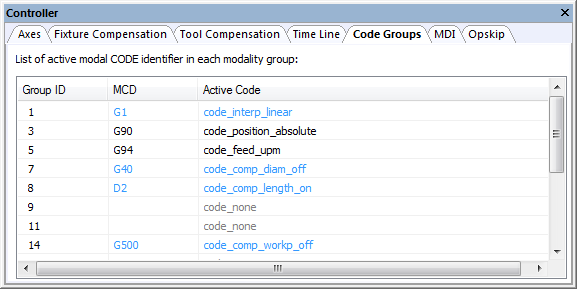
The CERUN»Code Groups window now lists the codes by their MCD representation as well as by their CeRun code_xxx name. E.g., G90, code_position_absolute. This feature was added in V20-1307.
If the Control-Out and Start-of-DISPLAY characters are the same (General Description / Output Format questions #2.6 and #16), then CeRun will resolve the ambiguity by assume all such text is tape commentary and will not output it to the Console trace window.
Macros and Customization
All Products
The following macro enhancements apply to all products.
A new Declaration Macro is available at the top of the Startup/Shutdown Macros section during post-processor, model and control emulator macro development. This macro in combination with a new “strong declaration” feature are designed to help developers create more stable macro code and catch misspellings and improper use of variables in Quest instead of at run-time (if at all).
The purpose of the declaration macro is to provide a standard place where GLOBAL, OBJECT and FUNCTION variables can be declared and optionally assigned an initial value. No other commands can be specified in a declaration macro.
A new Strong Declaration setting is now available when compiling macros. There are 3 settings that control how strict the macro processor is concerning where and when variables are declared.
OFF: Variables can be declared when and wherever desired, in the same way as they always have. This is the default setting.
PARTIAL: GLOBAL, OBJECT and FUNCTION variables can only be declared in the new Declaration Macro. LOCAL variables do not have to be declared.
FULL: Same as PARTIAL, but LOCAL variables must be declared in a macro before being used.
The Full interface Tools»Preferences dialog Debug tab also permits the Strong Declaration setting to be changed at run-time (this setting is stored in the Registry and shared with Quest). The Debug tab also has a new “warn about uninitialized variables” setting, that when selected will diagnose whenever a macro variable is used in an expression before it has been assigned a value. The macro processor has a default assignment that it has always used in such cases, but it is not good programming practice to rely on these defaults, and in some cases this may be unintended.
The macro processor now supports a SEQUENCE type in the DECLAR command, to strongly declare a variable as being a sequence type.
The DECLAR command now allows arrays to be declared having up to 4 dimensions (the previous limit was 1). For example, DECLAR/REAL,TABLE(100,3) defines an array of 100 rows and 3 columns. Some points of note:
Arrays are possible for all data types excluding sequences (a sequence is a variable-length single-dimensioned array).
String arrays will now have a fixed length of 256 characters per string element, which is the maximum string length permitted by the macro processor. In earlier releases strings in arrays had a length of 80 characters unless RESERV was specified to change the length. RESERV is not available for multi-dimensioned arrays and has been removed from the documentation.
Variables can now be assigned a value at the same time as they are created with the DECLAR command. To assign a value to the variable being declared, simply follow the variable name with an “=expression” assignment. Sequences can be assigned values when created by following the sequence variable name with an “={expression-list}” assignment. Arrays cannot be assigned values when declared. For example:
Added support for the +=, –=, /= and *= macro operators commonly used in C and other programming languages. These operators provide the following functionality when used with numeric variables and constants:
V21 V20
A+=B A=A+B
A–=B A=A–B
A/=B A=A/B
A*=B A=A*B
The += operator can also be used with sequence and string variables and constants, to append one sequence to another, or one string to another.
V21 V20
A+={B} A={A,B}
A+=B A=A//B
External functions have always required a link between the DECLAR/EXTERN,FUNCTN command in the macro processor and the DLL (dynamic link library) file on the computer that contains the compiled code of the external function. These external function DLLs can now be copied into the Quest file storage section, and then referenced in the DECLAR command using the ICAMFS universal URL. For example:
DECLAR/EXTERN,FUNCTN,’//ICAMFS/code.dll’,name(arguments)
Similarly, EXE (executable) files can also be copied to the Quest file storage section, and then referenced in the SYSTEM command using the ICAMFS universal URL. For example:
SYSTEM/’//ICAMFS/name.exe arguments’
This simplifies distribution and versioning of post-processors, control emulators or models that would normally have relied on external libraries or other executable programs.
New Output Format Descriptors are now available to handle spacing and sequence numbers in the output string.
New !(Tn) and !(tn) “tab” output format descriptors advance to the specified character position “n” in the output string and then continue output from there. The uppercase !(Tn) descriptor advances to the specified character position or to the end of the string, whichever is higher. The lowercase !(tn) descriptor will position to the specified character, truncating the string if it is larger. These format descriptors are designed to simplify the generation of tabulated output.
New !(@N) and !@N predefined sequence number output format descriptors can be used to output either a specified N block value, or the next N block in sequence. These format descriptors are designed to provide control over sequence numbering in INSERT commands when automatic output of N blocks with INSERT is disabled.
A new !(F+sn.ns) numeric output register format is available to output a value with a fixed output width. It is similar to the !(X+sn.ns) format, except that the ± sign floats to the left of the first digit rather than occupying the first column of output.
Some improvements have been made to macro CASE processing.
When tracing a CASE statement in the Source window using the Debug»Step Into or Step Over functions, processing now skips directly to the matching WHEN condition. In prior releases, you had to step past each non-matching WHEN before reaching the matching WHEN, which was inconvenient on large CASE blocks. Non-matching WHEN conditions are no longer traced in macro output.
The Quest macro compiler now accepts constant system variables $PI, $TRUE, $FALSE and $NULL as matching WHEN conditions. These are the only variables that are allowed in a WHEN statement.
The following general functions are new for this release:
Name |
Type |
Description |
|---|---|---|
$FGCYPT3() |
S equence |
Create cylinder from 3 points |
$FGPLPTN() |
S equence |
Plane canonical form given point and normal |
The $FGCYPT3(p1,p2,p3) function returns an {x,y,z,i,j,k,r} sequence defining the center, vector and radius of a cylinder constructed through 3 points, each defined as an {x,y,z} sequence. The cylinder axis is perpendicular to a plane constructed through the 3 points, and has the 3 points along its circumference. $NULL is returned if the points all lie on the same line.
The $FGPLPTN(point,vector) function returns a {d,i,j,k} sequence of a plane that passes through a point defined by an {x,y,z} sequence and is perpendicular to a vector defined by an {i,j,k} sequence.
The following general variable is new for this release:
Name |
Type |
Description |
|---|---|---|
$SEQALLOC |
Numeric |
Sequence allocation size/strategy |
The $SEQALLOC variable defines how internal memory should be allocated when sequence variables are created and when they grow in size. This increase in size occurs when the new += operator is used to append to an existing sequence, or when a sequence variable is overwritten by a larger sequence, as in A={A,B} or even A={B}. Note that internal allocation size is not the same as the actual size of a sequence as determined using $FLEN().
This subject is covered in more detail in the documentation, but in brief, setting $SEQALLOC=0 (the default) will generally result in significantly faster macro processing of sequences, whereas setting $SEQALLOC=1 will maintain the same allocation strategy and speed as for earlier releases.
CAM-POST
The following macro enhancements apply when using CAM-POST.
A new Register Macro is available when post-processing. This macro is run whenever a matching register is to be output. The macro provides the following $P variables:
$P1 Set to 0 on return to inhibit output of register
$P2 String containing the formatted register value
$P3 Register index number in the Register Table
$P4 Unformatted value of the register
The $P2 value contains the formatted register value that will be output to tape when the macro exits. $P2 can be changed in the macro (in the same way that $P3 can be changed in a Tape Macro). Setting $P1=0 inhibits the output of the register value.
A new $FREGFMT(n) function returns a $FSWRIT() compatible output format descriptor of a register index “n”, which can be used to modify the $P2 formatted register value as a function of the $P4 unformatted register value. For example, to output SIN instead of degrees:
$P2=$FSWRIT($FREGFMT($P3),$FSIN($P4))
By default the register macro executes for every register that is output. This default behaviour can be changed by using the new $REGMAC and $REGMATCH variables described on page 32.
The PPFUN/23 command provides new options to enable/disable the recording of travel and timing information.
PPFUN/23,ON-OFF enables/disables the recording of tool travel information. When disabled, travel information is not updated in the $TLMIN-MAX variables, nor in the listing, nor is travel checked for diagnostic and path-planning purposes.
PPFUN/–23,ON-OFF enables/disables the recording of timing information. When disabled, timing information is not updated in the $TLSUM variable, nor in the listing.
The following CAM-POST variables and functions are new or modified for this release:
Name |
Type |
Description |
|---|---|---|
$APIDS |
Numeric |
Id of SmartPATH generated motion |
$FREGFMT() |
String |
Returns $FSWRIT compatible format for register |
$KIT |
String |
Name of CAM interface kit |
$LABINC |
Numeric |
Label increment amount |
$LABNO |
Numeric |
Current label number |
$REGMAC |
Logical |
True to enable register event macro |
$REGMATCH |
S equence |
List of registers to match |
$SKIPCOD |
Numeric |
Skip code function status |
$SKIPERR |
Numeric |
Skip code alarm behaviour |
$SPACE |
Logical |
Set to enable spacing between registers |
$TLSUM |
Numeric |
$TLSUM(6-7,n) lists min-max RPM by tool |
The $APIDS variable when non-zero indicates that the current motion sequence was generated by SmartPATH during an entry from or exit to a reference home position. When $APIDS is less than 0, $FAPPOS(1) returns the entry position in workpiece coordinates. When $APIDS is greater than 0, $FAPPOS($APIDS) returns the exit position in workpiece coordinates.
The $FREGFMT(reg) function takes as input either a register index number, or a text string matching one or more characters of a register’s descriptor. It returns a format string that can be used with the $FSWRIT() function to output a register value. This function was designed to be used in the register macro to modify register values. E.g., $P2=$FSWRIT($FREGFMT($P3),ƒ($P4))
The $KIT variable contains the name of the CAM interface kit, or is blank if an interface kit is not being used.
The $LABINC variable holds the label number increment. This increment is added to the current label number after a label is output to generate a new current label number.
The $LABNO variable contains the current label number to use if a label is required to be output.
The $REGMAC variable controls execution of the register macro. The register macro is executed only if this variable is set to $TRUE. It is initialized to $TRUE by Gener. If it is set to $FALSE, the register macro will not be executed.
The $REGMATCH sequence variable defines the registers that are candidates for matching with the register macro. If empty or $NULL, all registers are candidates for matching. The $REGMATCH sequence can contain zero or more register index numbers and zero or more text strings matching one or more characters of a register’s descriptor.
The $SKIPCOD variable indicates the current probe “skip code” status. A value of 0 indicates that skip code processing is not active; a value of 1 indicates the function is active. When active and simulation is enabled, a probe touch event stops further axis motion for the current block. This variable is settable.
The $SKIPERR variable indicates the probe “skip code” state recorded at the end of the last motion. A value of 0 indicates no error. A value of 1 indicates a touch event occurred. A value of 2 indicates that a touch event did not occur.
The $SPACE variable controls the output of register spacing. Register spacing is enabled when this variable is set $TRUE and register spacing is supported (Quest General Description / Output Format question #2.5 “SPACE code”). It is initialized to $TRUE by Gener. If it is set to $FALSE, then spacing will be disabled on subsequent output.
The $TLSUM variable now includes two additional columns recording spindle speed information. $TLSUM(6,n) is the minimum speed in RPM used by tool n. $TLSUM(7,n) is the maximum speed in RPM used by tool n. The minimum and maximum spindle speeds are initialized to zero, and are recorded at the endpoint of each motion if the spindle is turning.
Virtual Machine
The following macro enhancements apply when using Virtual Machine.
The following functions have been added to provide for the dynamic creation of tools and holders at run-time. These functions could be used in cases where a Manufacturing Extractor does not exist (which would normally create tools automatically), but where the CLDATA is “rich” enough to provide detailed descriptions and dimensions of tools and holders.
Name |
Type |
Description |
|---|---|---|
$FMSTOOL() |
Numeric |
Dynamic tool creation |
$FMSHLD() |
Numeric |
Dynamic holder creation |
$FMSCOLR() |
Numeric |
Colour definition for dynamic tools and holders |
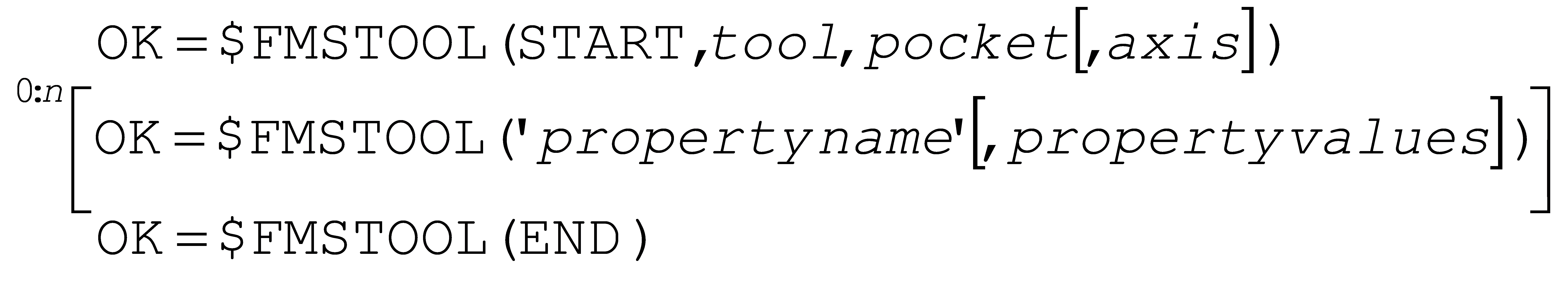
The $FMSTOOL function provides the ability to dynamically create a tool under macro control using the same functionality as can be found in the Simulation»Tools dialog. Tools are created by calling $FMSTOOL in the following sequence:
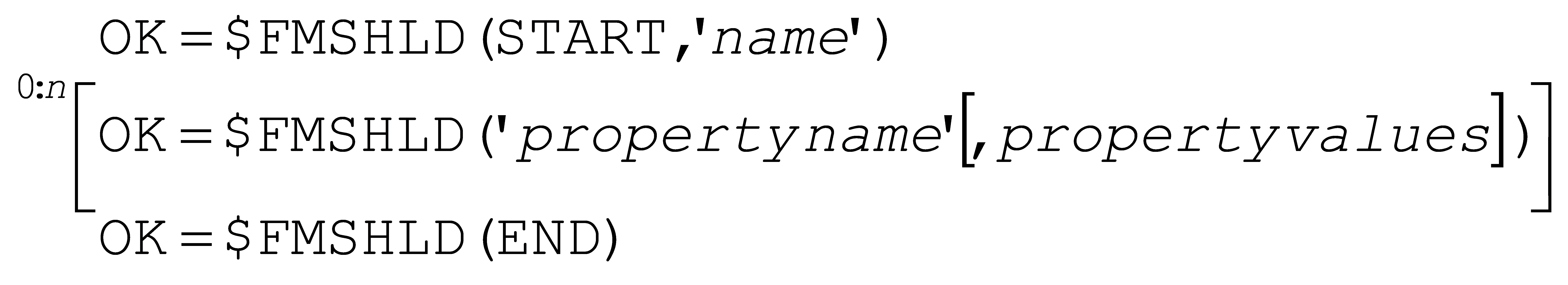
Similarly, the $FMSHLD function provides the ability to dynamically create a holders using the same functionality as can be found in the Simulation»Holders dialog. Holders are created by calling $FMSHLD in the following sequence:
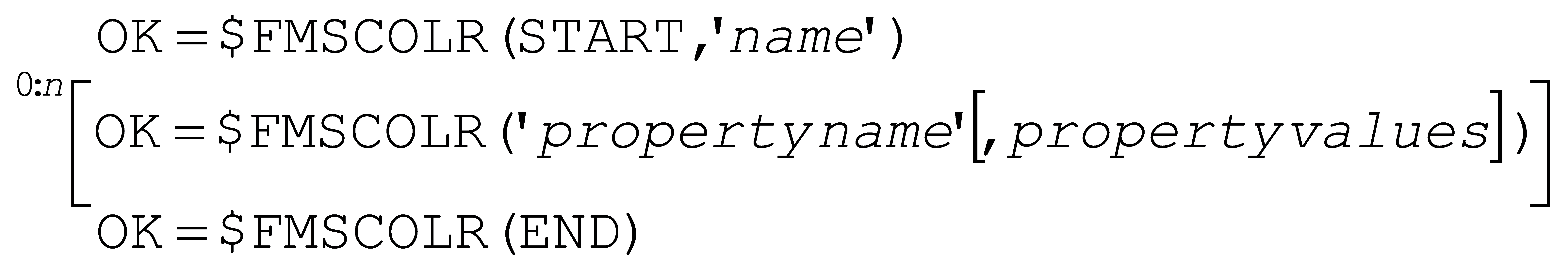
Finally, the $FMSCOLR function provides the ability to define the material properties of the tool and holder, using same functionality as can be found in the Simulation»Material dialog. Materials are created by calling $FMSCOLR in the following sequence:
The following Virtual Machine functions are also new for this release:
Name |
Type |
Description |
|---|---|---|
$FMSESF() |
Numeric |
Export Stock File |
$FMSTPS() |
Numeric |
Set Tool-Path Style and colour |
$FMSSETUP() |
Logical |
Load the next or specified setup |
The $FMSESF(…) function exports the in-process stock (from material removal simulation) to a file on disk in STL format. Various options of this function can be used to output individual or all stock components into separate files, or combined together into a single file. This function can be called multiple times in a Virtual Machine session.
The $FMSTPS(…) function changes the visual representation of the tool-path trace shown in the simulation window. A custom tool path style is defined as follows:

The RGB values are numbers in the range 0-255. The width is of the trace line is defined in pixels in the range 1-5. The style is a number in the range 1-5 defining various predefined line styles. The custom style is modal until changed by another call to $FMSTPS. Custom styles are only applied between calls to $FMSTPS(ON) and $FMSTPS(OFF).
The $FMSSETUP([n]) function changes to the specified or next setup number as defined in the Simulation»Manager window Setups group . When called with a setup number, the simulation window will be updated to show the part, stock and fixture components as defined by the specified setup, where setup number 1 is the default at the start of processing. When called without a setup number, the next higher setup will be selected.
Control Emulator
The following macro enhancements apply when using Control Emulator.
The following Virtual Machine functions are available with CeRun when running with the integrated interface to DELMIA V6:
Name |
Type |
Description |
|---|---|---|
$FMSID() |
Numeric |
New option to get DELMIA object ID |
$FMSIDT() |
Numeric |
New option to get DELMIA object type |
$FMSIDN() |
Numeric |
New option to get DELMIA object name |
$FMSMOVE() |
Logical |
Move axis to specified position |
The V6 interface to DELMIA permits the movement of auxiliary axes of the model. The above listed VM functions were enhanced to provide the same functionality with DELMIA as they normally do when running with Virtual Machine. The $FMSID functions can return information about DELMIA axes; the $FMSMOVE function can be used to move DELMIA model axes.
The following Control Emulator functions and variables are new for this release:
Name |
Type |
D | e | s | c | r | i | p | t | i | o | n | * | * | |
|
|---|---|---|---|
$FREGFMT() |
String |
R e t u r n s $ F S W R I T c o m p a t i b l e f o r m a t f o r r e g i s t e r |
|
$OPNAME |
String |
O p e r a t i o n n a m e |
|
$SKIPCOD |
Numeric |
S k i p c o d e f u n c t i o n s t a t u s |
|
$SKIPERR |
Numeric |
S k i p c o d e a l a r m b e h a v i o u r |
|
$TLNAME |
String |
T o o l n a m e |
|
$TLSUM |
Numeric |
$TLSUM(6-7,n) lists min-max RPM by tool |
|
The $FREGFMT(reg) function takes as input either a register index number, or a text string matching one or more characters of a register’s descriptor. It returns a format string that can be used with the $FSWRIT() function to output a register value. This function can be used with EXEC commands to produce NC code that conforms to the register format.
The $OPNAME variable can be set to identify the name of the current operation. This information is used in the Statistics window as well as in the simulation Time Line window and HUD display.
The $SKIPCOD variable indicates the current probe “skip code” status. A value of 0 indicates that skip code processing is not active; a value of 1 indicates the function is active. When active and simulation is enabled, a probe touch event stops further axis motion for the current block. This variable is settable.
The $SKIPERR variable indicates the probe “skip code” state recorded at the end of the last motion. A value of 0 indicates no error. A value of 1 indicates a touch event occurred. A value of 2 indicates that a touch event did not occur.
The $TLNAME variable can be set to identify the name of the next tool to be loaded. This information is used in the Statistics window as well as in the simulation Time Line window and HUD display
The $TLSUM variable now includes two additional columns recording spindle speed information. $TLSUM(6,n) is the minimum speed in RPM used by tool n. $TLSUM(7,n) is the maximum speed in RPM used by tool n. The minimum and maximum spindle speeds are initialized to zero, and are recorded at the endpoint of each motion if the spindle is turning.
CAM Interfaces
A new SYNEX command is available when reading APT source into the post-processor. This command is similar to the textual SYN command, except that it supports matching and substitution using regular expressions in the same way that the $FEDIT function does.

By default the substitution is applied individually to the case sensitive aptsource lines as they are read. Specify LAST to instead apply the substitution to the final record, which omits comments, concatenates continued lines, and (except for strings) removes all spacing and converts characters to uppercase.
TRACUT, INDEX and COPY commands can now optionally be processed during the conversion from aptsource input to internal binary CLDATA format.
TRACUT processing during aptsource input is controlled by the following command:

ON enables processing of TRACUT commands in the ANSI APT standard order TRACUT ⇨ COPY ⇨ TRACUT/LAST. LAST enables processing in the CATIA order COPY ⇨ TRACUT ⇨ TRACUT/LAST. OFF (which is the default) passes TRACUT commands unmodified to the post-processor. Note however that the post-processor does not support TRACUT.
INDEX and COPY processing during aptsource input is controlled by the following command:

ON enables processing of INDEX and COPY commands. OFF (which is the default) passes INDEX and COPY commands unmodified to the post-processor, where they can either be expanded or converted to subprogram processing depending on Quest or DEFSUB/INDEX command preferences.
APT processors from different vendors have applied nested COPY matrix multiplication in different ways. The following command defines the matrix multiplication order:

ON performs nested COPY matrix processing in the same order as is used by CATIA and by APT/AC. OFF (which is the default) conforms to the order used by CAM-APT-SURF, APT-III, APT-IV and APT 360.
The CIR_DIR definition file symbol now permits a NONE setting (in addition to CLW and CCLW) in support of the Featurecam CIRCLE command. This setting ignores the circle command vector and instead takes the shortest path to the arc end-point.
Siemens NX 7.0 and higher now support an ICAM_CLSF template that can be used in place of the CLSF_ADVANCED or CLSF_STANDARD, to produce aptsource that directly conforms to ICAM requirements. The ICAM template provides a much more complete conversion of MOM data to aptsource, and also corrects for a number of problems in the NX supplied templates, which are no longer being maintained by Siemens.
All Manufacturing Extractors have been enhanced to eliminate the requirement for a config.xml file to be present defining extractor options. The additional information that used to be required in the config.xml file is now obtained directly from the selected post-processor, model or control emulator.
Manufacturing extractors have been “unified”, meaning that they have a common interface and behaviour. The interface has been simplified, to present the manufacturing process data in as clear and complete a fashion as possible, and to reduce as much as possible the requirement to input additional data to obtain a complete extraction.
Manufacturing extractors also have a flexible tool control, which captures the tool alignment from the CAM system, and intelligently applies it to the model. The user has full control over the orientation and location of tools in the model, for example choosing between upper and lower turrets of a merging lathe.
Manufacturing extractors are also now being enhanced to support the concept of multiple setups. Initially, varying degrees of multi-setup support are available for CATIA, Creo2 and Mastercam X8. These and other extractors will continue to be enhanced for multi-setup support as resources permit.
The following is a list of current extractors and the more significant enhancements that have been made since the last release.
Dassault Systèmes – CATIA V5
Detailed manufacturing process tree control
Support for lathe grooving tools (round, trigon, groove)
Support for milling User Representation tools
Support for P0-P9 tool nose radius compensation
Multi-setup
Improved the stability and speed of extractor startup
CNC Software – Mastercam
Automatic identification of stock, part and fixture
Detailed manufacturing process tree control
Flexible control of NCI output
Multi-setup
Support Mastercam for Solidworks
Siemens – UGS NX
Detailed manufacturing process tree control
Generation of CLS by operation groups
PTC – Creo
Detailed manufacturing process tree control
Support NC-sequence and tool linked to NC-sequence
Support for multiple tool nose radius compensation
Support for milling User Representation tools
Support for BackPlotting and PlungeMilling tools
Support for inactive operations
Multi-setup
The Hypermill CAM interface has been continually enhanced to allow for more complete post-processing of milling and mill-turn manufacturing processes. These enhancements are also available under V20.
The TopSolid CAM interface now generates a #1004:1 record, which provides the following additional tool information (variable names are from TopSolid documentation). This enhancement is also available in V19-1437 and V20-1437.
#1004:1/1,<MagNum>,<MachineElem>,<keyRef>
#1004:1/2,<MagNum>,<DbRef>
#1004:1/3,<MagNum>,<RefToolMocn>
#1004:1/4,<MagNum>,<Comm>
PQRs
The following is a list of corrections made to V21 as a result of customer related PQR’s. Corrections due to internally generated problem reports, user interface problems, as well as customer reports of an obscure nature, are not reported here. Most of these corrections are also available in updated releases of V20 (the updated release number is listed at the end of the description).
Security
** PQR** |
Description |
|---|---|
0 55071 |
The floating manager would fail to connect under ipv6. |
0 53406 |
The license server would fail on an update if the server icamflm.key file is read-only. |
0 53400 |
The upper limit of allowable server port numbers is extended from 32767 to 65535. |
0 03482 |
The ICAMID utility test for a server is now more tolerant of networks with a high degree of latency. [080-1439] |
0 03377 |
The ICAMID and License Manager utilities now each check if the other is running and output a diagnostic to that effect (since they both require exclusive access to the same resources). [080-1405] |
0 03168 |
The floating license server had issues locating the icamflm.key file on new installations. [080-1318] |
CAM-POST
** PQR** |
Description |
|---|---|
0 03533 |
The user-dialog section was listing binary encoded image data in the Quest listing file and section summary. [V20-1449] |
0 03531 |
Macro “OPEN/unit,REAR” was opening files for overwrite instead of opening for append on UNIX systems. [V20-1449] |
0 03487 |
Setting $PNMODE=-1 in a macro resulted in the default absolute or incremental code being output with every motion. [V20-1441] |
0 03467 |
A SPINDL command could generate an unwanted M1 when the spindle was not controlled by M codes. [V19-1435,V20-1435] |
0 03459 |
The $FCL() function returned strings truncated at 80 characters. It now truncates (if necessary) at the 256 character maximum. [V20-1431] |
0 03456 |
The user-dialog “drop down” list control was missing the vertical scroll bar. [V20-1430] |
0 03455 |
There was a possible infinite loop when LIMIT/ORIENT is specified. This condition was more likely to occur when both LCS and CYCLE were active. [V20-1430] |
0 03447 |
Removed the option to disable the user-dialog group box, since Windows does not support this functionality. [V20-1425] |
0 03444 |
LIMIT/LENGTH was not being applied to the travel summary linear axes on motions where only the rotary axes were moving. [V20-1423] |
0 03436 |
Gener was not outputting automatic clamp/unclamp codes for the sub-spindle. [V20-1420] |
0 03435 |
Empty G0 blocks would appear sometimes in SmartPATH positioning sequences. [V20-1420] |
0 53612 |
User preference (2 rotary) LCS rotation computed an seemingly random solution resulting from an invalid radian to degree conversion when using $LCAUTO=2. [V20-1419] |
0 53544 |
User preference (2 rotary) LCS would fail to compute a solution if the input matrix could not be exactly represented. Processing now degrades gracefully, with the local Z aligned at a minimum. Also corrected a problem that unnecessarily split rotation and translation over 2 blocks. [V20-1418] |
0 03428 |
ROTABL/INCR could produce extra G0 Cangle blocks when a singular table is rotated. Problem was introduced in build 1122. [V19-1418,V20-1418] |
0 03421 |
CAM-POST had problems dealing with the situation where circular interpolation and diameter compensation, when active together, each required different G17/18/19 plane codes. [V20-1417] |
0 03403 |
SAFETY command motion pattern was not being respected with the combination of: RTCP active; LINTOL/SCAN active, and $TLMODE=-1. [V20-1414] |
0 03392 |
SAFETY command motion pattern was not being respected with the combination of: RTCP active; LINTOL/SCAN active, and rapid linearization active. [V20-1412] |
0 03400 |
The Status bar on the Gener/CeRun interface would be disabled following a Rewind. [V20-1411] |
0 03382 |
The spindle face frame orientation was not working for turning operations or when APPLY/MILL was specified after a TURRET command. [V20-1407] |
0 03375 |
The $FLOOK look-ahead function was causing the software to abort when used on a 4-axis wire edm. [V20-1405] |
0 03371 |
Macro files (.mac) would not compile if missing a linefeed character after the ENDMAC command. [V20-1405] |
0 03365 |
The TOOL(t) field in the diagnostic summary did not match the current tool number on machines using “ID” type tools. [V19-1403,V20-1403] |
0 03364 |
The default cutter length compensation offset number did not match the current tool number on machines using “ID” type tools. [V19-1403,V20-1403] |
0 03351 |
A $PNMODE setting in a macro could be unexpectedly changed by circular interpolation. The MODE command was not affected. [V20-1400] |
0 03349 |
SAFETY command motion splitting would generate a G0 code alone on a block, when in incremental positioning and the axes deltas for the intermediate motion were all zero. [V20-1352] |
0 03339 |
The $FLOOK look-ahead function was causing the software to abort in a composite or mill-turn post-processor, if the look-ahead started in one component and completed in another. [V20-1351] |
0 03335 |
Tool diameter value $TLTAB(1,11) was not updated for a dummy tool. [V20-1351] |
0 03320 |
Subprogram processing (DEFSUB-ENDSUB-CALSUB) failed following a call to the $FLOOK() function or an Operation Event macro. [V19-1349,V20-1349] |
0 03322 |
$FLOOK() had problems restoring string data from the future, causing other local and/or global variables to be overwritten. [V19-1348,V20-1348] |
0 03316 |
LIMIT/ORIENT was not being respected when SmartPATH was active. [V20-1346] |
0 03310 |
There was a problem with registers being unexpectedly changed when navigating backwards in the New-Post and Modification wizards. [V19-1345,V20-1345] |
0 03263 |
PPFUN modal changes were not being properly segregated between the main and side turrets of a merging lathe, when processing switched back and forth between the turrets. [V19-1344,V20-1344] |
0 51542 |
The New-Post and Modification wizards were missing some new V20 features. [V20-1339] |
0 03294 |
The MOVETO command now respects axis modality as defined by the PPFUN/12 command. [V19-1339,V20-1339] |
0 03289 |
The Gener full interface Source window had issues stepping into and viewing subprogram source. [V20-1338] |
0 03283 |
Invalid overtravel in polar output could occur with circular interpolation when the circle center had a different x-axis (polar interpolation axis) sign than the start and end points. [V19-1337,V20-1337] |
0 51380 |
The $FTLTAB look-ahead function was causing unexpected data to be written to the HTML listing navigator. [V20-1336] |
0 03281 |
Corrected an issue with the Gener and CeRun launch panels where newly saved Config settings would not be used. [V20-1336] |
0 03213 |
Deprecated using the current working directory as an ICAM.DEF file location, since concept of current directory can be confusing on Windows systems. The Config utility will no longer make that choice available. [V20-1335] |
0 51152 |
RMD actions to enable/disable the OE macro were missing. [V20-1334] |
0 51112 |
$OE.P1 and $INFO.P1 were returning the intermediate position of a split positioning motion rather than the endpoint of the first positioning motion. [V20-1334] |
0 03253 |
The $FTLTAB was not reporting redundant tool changes (i.e., when the same tool number is loaded multiple times in succession). [V19-1329,V20-1329] |
0 03229 |
The Gener launch panel had problems differentiating between multiple versions and revisions of post-processors in the database. [V19-1326,V20-1326] |
0 03227 |
The CLAMP/MANUAL command was not diagnosing an out-of-travel condition, and subsequent motions would also not diagnose the condition since the axis was already out of travel. [V19-1325,V20-1325] |
0 03225 |
There was a possibility of mill-turn incorrectly thinking a polar start positioning motion was out of travel, which then resulted in an unnecessary TTO positioning motion to the polar start position. NC program runs correctly. [V20-1325] |
0 03205 |
Deprecated the LANG environment variable, which was the source of ‘language “C” not supported’ messages. Language settings are now controlled only by the Config utility. [V19-1322,V20-1322] |
0 03190 |
The user dialog could loop endlessly or cause the software to abort when using picture controls. [V20-1320] |
0 03184 |
Problems with the combination of PQ diameter compensation and 3D circular interpolation could produce “results unpredictable” diagnostics. [V20-1320] |
0 03182 |
A deferred coolant on plunge was not recognizing a motion originating from the reference home position as a plunge. [V20-1320] |
0 03181 |
A reference home type machine, with question #15 “Use default starting position for calculations” answered in the affirmative could result in “?????” listed in the linear coordinates column throughout the entire Gener listing file. [V20-1320] |
0 03160 |
Quest could abort processing when dragging a file out of the File Storage section and into Windows Explorer (Vista and higher). [V19-1317,V20-1317] |
0 03156 |
The Gener full interface could possibly break in a macro although the breakpoint was actually set on the CL file. [V19-1316,V20-1316] |
0 03142 |
The default tape file extension as specified in Quest was being ignored when the post-processor was selected by a MACHIN statement instead of explicitly by name. [V20-1315] |
0 03133 |
The SAFETY command processing had problems dealing with RAPID linearized TTO (tool-tip-only) motions, causing linearization to fail. [V20-1314] |
0 03131 |
The tool change shutdown macro (but not the startup) was being incorrectly run when a TURRET command failed due to syntax errors. The LOAD and LOADTL commands do not have this behavior. [V19-1313,V20-1313] |
0 03130 |
The Quest tool change section question #163 “Repeat travel errors at the start of the new operation” answered in the affirmative was not working for tool changes invoked using the TURRET command. [V20-1313] |
0 03125 |
An “LCS/ZXROT,180” command resulted in “A local coordinate system rotation test has unexpectedly failed” diagnostic when using the Euler format. [V20-1313] |
0 03124 |
The LIMIT/ROTREF command had no effect on B-axis rotary table when used in combination with a 90-degree tool holder. [V20-1313] |
0 03101 |
Attempting to access individual elements of $OE and $INFO sequence variables, using the $name(index) syntax, would return the index value instead of the sequence value at that index. [V20-1311] |
0 03080 |
When both models and post-processors were loaded into Quest, then a “Diff” between post-processors would sometimes be disallowed. [V19-1304,V20-1304] |
Virtual Machine
** PQR** |
Description |
|---|---|
0 03481 |
Corner radius compensation was incorrect when machine units did not match the VSW file units as defined in the Simulation Controller window. [V20-1438] |
0 54630 |
The Model Diff utility was not comparing model macros. |
0 03476 |
The Virtual Machine tool-path was not following the tool-tip on the first motion following a tool change. [V20-1437] |
0 03470 |
Material removal simulation could intermittently and unexpectedly be disabled during multi-channel processing. [V20-1436] |
0 54452 |
Improved the speed of Diagnostic window processing, which is especially noticeable when there are many diagnostics. [V20-1435] |
0 03448 |
Incorrect circular motion when not in the XY plane and using RTCP on a dual rotary table machine. [V20-1426] |
0 03441 |
On controls without a diameter compensation offset switch feature, the length compensation offset switch will now be used for both. [V20-1422] |
0 03440 |
Error handling has been improved when reading problematic STL files. [V20-1421] |
0 03415 |
A false “tool rapids into stock” diagnostic would occur on a RTCP feed motion where the motion was rotating about a stationary tool-tip position. [V20-1414] |
0 03414 |
Controller fixture compensation was not being saved/restored in look-ahead, causing future changes to affect current motions. [V20-1414] |
0 03407 |
Removable head devices might not interchange properly when moving forwards and backwards in Timeline. [V20-1412] |
0 03404 |
Diameter compensation is now supported in the YZ and ZX planes. [V19-1413, V20-1413] |
0 03394 |
The $FMSGCS() function was not accounting for the effects of fixture compensation. [V20-1410] |
03285 |
The WCS marker could be incorrect for dynamically created models or when the machine base frame did not match the world base frame. [V20-1401] |
0 52234 |
The model was not marked as modified in Quest when a change was made to the model properties. [V20-1351] |
0 03336 |
The camera position is now being remembered (i.e., saved in the VSW file) on a Rewind and between sessions. [V19-1351,V20-1351] |
0 03304 |
The $LCS macro variable setting in Gener and CeRun was not being processed by Virtual Machine. [V20-1341] |
0 03303 |
A multiple-axis reference GOHOME was not moving some model axes. [V20-1341] |
0 03191 |
The $FMSATA() function would cause the attached object to lose its collision testing attribute. [V20-1320] |
0 03166 |
Corrected a problem with stock transfer that would sometimes not position the in-process stock at the proper place. [V20-1320] |
0 03150 |
Length compensation was being incorrectly activated on rotary-only motions, resulting in unexpected linear axes motion. [V20-1318] |
Control Emulator
** PQR** |
Description |
|---|---|
0 55404 |
With a composite CE, the $FAPPLY() function now calls the shutdown macro of the old component CE followed by the startup macro of the new component CE. |
0 55160 |
Siemens pre-processor: Now supports the R0 variable. Now recognizes $Rn and $R[n] variables. Subprogram search now checks the entire file instead of just the remainder. |
0 54848 |
Toggling “edit source” now maintains the vertical scroll position. |
0 54485 |
The “positioning mode is not known” diagnostic was not tested properly; new “working plane is not known” diagnostic added. |
0 03489 |
The $FAPPLY() function will now copy matching code group states from the source CE to the target CE. [V20-1441] |
0 03484 |
MDI text will now appear in the Source window in the same way as a subprogram, to enable stepping and debugging. |
0 03420 |
The Fanuc pre-processor now accepts sub-parameters with variable values. [V19-1415,V20-1415] |
0 03418 |
The DELMIA model Z axis was moving on first XY-only motion following a tool change. [V20-1414] |
0 03402 |
A call to a missing subprogram would restart processing at the top of the current tape file, causing an endless loop. [V19-1412,V20-1412] |
0 03399 |
Using the $FGET() function with a start index of zero would cause the software to abort. [V19-1411,V20-1411] |
0 03391 |
Circular motion could fail if it occurred on a block immediately following a change of LCS or RTCP. [V19-1410,V20-1410] |
0 03379 |
Threading was not setting the lead value correctly unless a constant lead “special feedrate register” was being used. [V20-1405] |
0 03367 |
CeRun now recognizes and diagnoses operator messages that are missing the closing delimiter. [V19-1404,V20-1404] |
0 03272 |
Control emulator code/data customization was being omitted when upgrading the database. [V19-1335,V20-1335] |
0 03260 |
Incorrect unwinding could occur on a rotary motion to home. [V20-1332] |
0 03208 |
There was a problem with the “advanced expression” code matching causing the same macro to fire multiple times on the same block. [V19-1330,V20-1330] |
0 03250 |
A missing cancel-cycle code is now diagnosed. [V20-1329] |
0 03229 |
The CeRun launch panel had problems differentiating between multiple versions and revisions of control emulators in the database. [V19-1326,V20-1326] |
0 03207 |
The CeRun license was not released if the program exited with a Fatal error. [V19-1322,V20-1322] |
0 50542 |
The Fanuc preprocessor was not correctly processing G66 and G66.1. [V20-1321] |
0 03139 |
Setting $ERRMSG=$FALSE would still result in some error messages being output. [V19-1321,V20-1321] |
0 03173 |
CeRun macro processing would fail when using OBJECT scope variables of type STRING. [V20-1319] |
0 03123 |
Stepping into a macro (F11) would often break only on the second line. [V20-1312] |
0 03106 |
Siemens additive LCS code without parameters, e.g., AROT alone, was resetting LCS to identity. [V19-1311,V20-1311] |
0 49856 |
Quest Code Customization showed an incorrect MCD representation for codes defined using “DATA as value”. [V20-1308] |
0 03033 |
The Fanuc preprocessor now accepts word addresses in any order on subprogram call blocks. [V20-1307] |
Macro Processor
** PQR** |
Description |
|---|---|
0 03463 |
Using a calculated value for an array element specification could result in the next lower index being used, because the internal conversion from real number to integer index was not accounting for the imprecise nature of floating point values. [V20-1432] |
0 03348 |
The upper limit for user variable names is 32 characters but V20 was incorrectly limiting names to 31 characters. [V20-1352] |
0 03231 |
User declared external functions were incorrectly being listed in the variable watch window. [V20-1326] |
0 03226 |
Duplicate declaration of macro variables was failing. Macro processor now allows variables of lesser scope to be re-declared (e.g., local overrides global). Any uninitialized variable can now be re-declared. [V20-1326] |
CAM Interfaces
** PQR** |
Description |
|---|---|
0 03488 |
TopSolid interface now supports FINCUT and ATANGL options with the THREAD command. [V19-1441,V20-1441] |
0 03488 |
TopSolid interface now supports OSETNO option with the LOADTL and TURRET commands. [V19-1428,V20-1428] |
0 53735 |
Mastercam interface was generating too many OPTYPE commands, for example, at every level of a pocket instead of once per pocket. [V20-1421] |
0 53422 |
When CONTRL/NX3DCOMP,ON was active, it caused problems with NX CLS file aptsource lines that were continued from one line to the next. [V20-1416] |
0 53735 |
Mastercam drill cycles produced incorrect results when “absolute” values were selected. [V20-1413] |
0 03376 |
TopSolid interface now supports changes in spindle speed midway through an operation. [V19-1405,V20-1405] |
0 03233 |
Mastercam interface had various problems with 3D tool compensation. [V20-1404] |
0 51312 |
MULTAX/OPTION command was only being recognized and processed when it was coded in a macro, and not from the CLDATA file. [V20-1336] |